In- and Outputs
A few inputs and outputs in evon Smart Home are used similarly in different modules. This is described in this section.
A few inputs and outputs in evon Smart Home are used similarly in different modules. This is described in this section.
A switch can be connected to a light module, blind module or a digital module. A switch has a pre-defined function for a light or blind module. Every switch can be simulated in evon Smart Home for test purposes.
These switches can be found under “all apps” – “switches”.
Naming
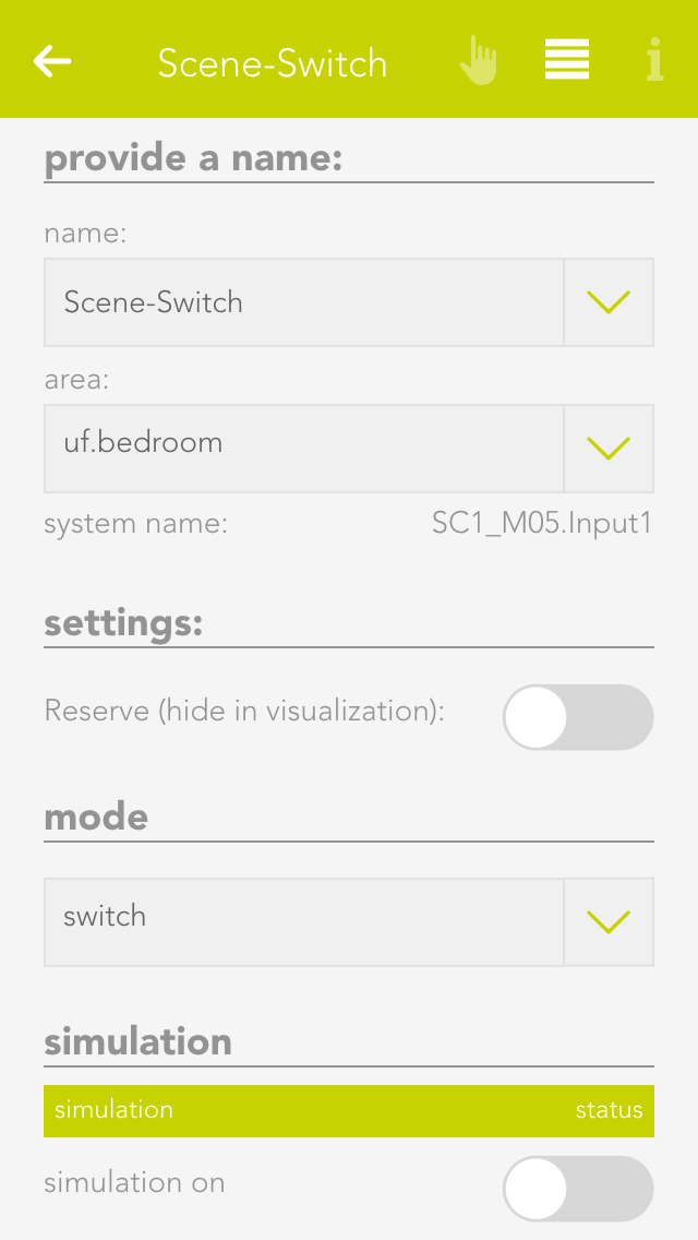
If you have connected your switch to a light or shading module, then the switch is automatically named according to the light or blind. If you wish to give it a different name, then deactivate the option “same name as blind/light” in the parameter panel and give the switch a new name. If you have connected your switch to a digital module, then you must name it yourself.
Reserve
If you have a switch in your system that you don’t use, then you can hide it by deactivating the option “reserve “hide in display” in the app “ switches”. To unhide it, you can find your switch in the app “hardware”.
Mode
If you want to change the mode, i.e. define the switch as a presence detector or a digital input, then you can do this in the parameter panel under “mode”. Not every module can change the mode however, or not all possibilities are available. This means that the light modules’ switch can only be converted to a presence detector. Switches for a blind element cannot be converted. Switches for digital modules have all three modes.
If you have linked a switch to a scene and would now like to simulate this scene, then there is no need to go to the switch and press it every time, you can use simulation to create the switch press. Simply activate the option “simulation” in the operator panel to see 3 buttons that you can use to simulate switch presses.
Warning: If you leave the simulation mode activated, the autonomous functions will not work!
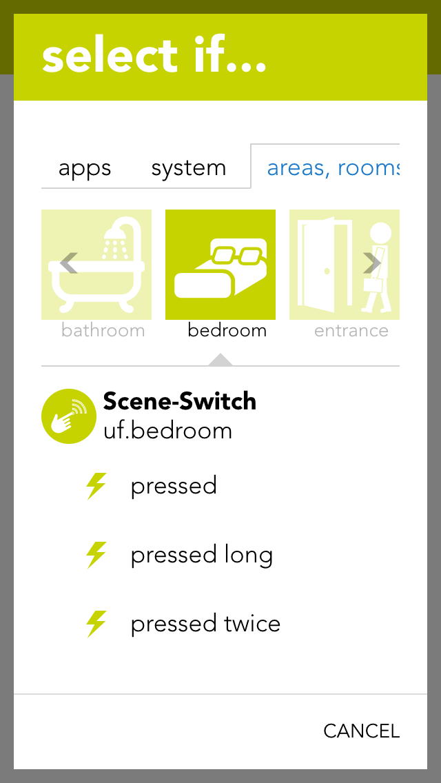
You can use the switches for a scene (assuming it as been named). In the scene “if …” just select the switch and decide if you want the scene to be executed after a single, double or long press.
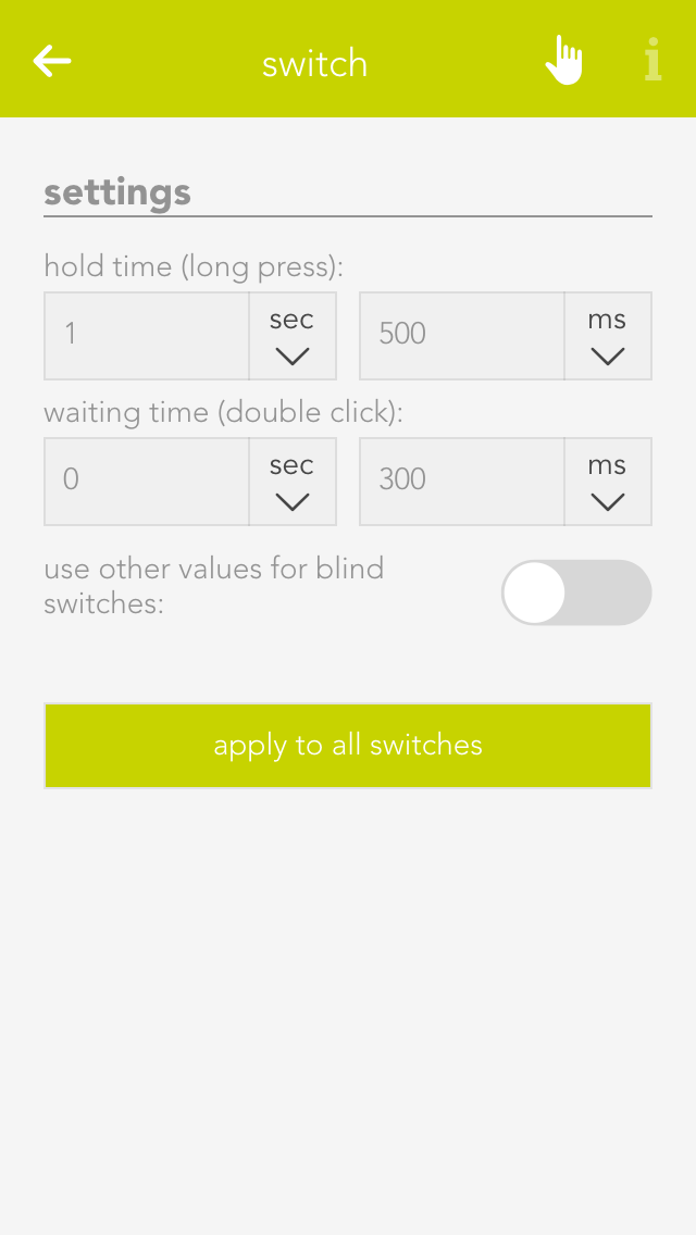
Open the switches settings (“all apps” – “settings” – “switches”) if you want to define the times for a press and double-press. Select the desired values and confirm them by clicking the button “use values for all switches”.
Hold time (long button press)
A switch must be pressed for at least thus time to be recognized as a long button press.
Wait time (double-press)
The gap between two switch presses must be as least as big as the defined wait time to be recognized as a double-press.
If you wish to define different values for a switch that is connected to a blind module, then activate the option “use other values for blinds”.
A motion detector can be connected to a light module or a digital module. The motion detector has a pre-defined function when connected to a light module. Motion detectors can be simulated in evon Smart Home for test purposes.
You can find motion detectors under “all apps” –“motion detectors”.
Naming
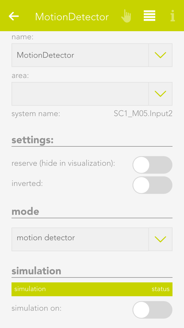
If you have connected a motion detector to a light module, then it is automatically assigned the same name as the light. If you wish to assign a different name, then deactivate the option “same name as light” in the parameter panel and enter the name you wish. If the motion detector is connected to a digital module, then you must assign it a name yourself.
Invert
If the motion detector is connected to a digital module, you have the possibility to invert the logic by activating the option “invert” in the operator panel.
Reserve
Should you have a motion detector in the system that you do not use, you can hide in from the app “motion detector” by activating the option “reserve (hide in display)” in the parameter panel. To unhide it, you will find your movement detector in the app “hardware”.
Mode
If you wish to change the mode, i.e. convert the motion detector input to a switch or a digital input, you can do this by changing the mode for the motion detector in the parameter panel. Not all modes can be changed in all modules, or not all possibilities are available. This means that a motion detector for a light module can only be changed into a button. All three modes are available for motion detectors for a digital module.
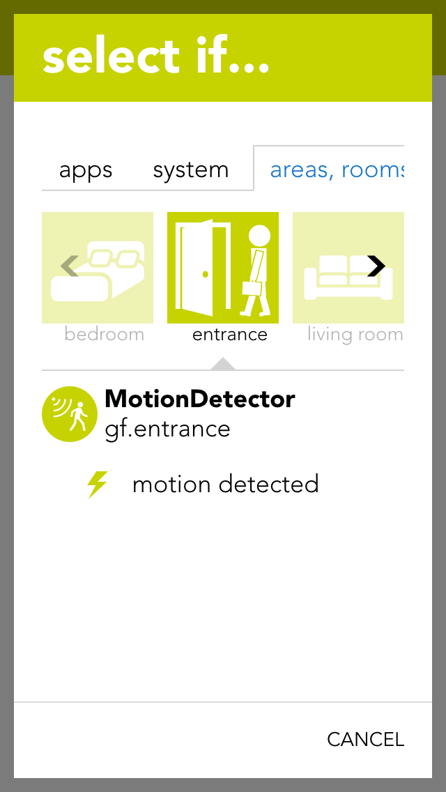
You can also use the motion detector for a scene (in as far as it has been named). In the scene, select the motion detector for “if …” and decide if you want the scene to be carried out on the rising or falling edge of the signal.
Rising edge
The electrical contact of the motion detector has been activated.
Falling edge
The electrical contact of the motion detector has been deactivated (after the internal time of the motion detector).
For example, if you have linked a motion detector to a scene and you would like to test this scene, then you do not have to go to the motion detector and activate it every time, you can change the state using simulation. Simply activate the option “simulation on” in the operator panel to see the option with which you can change the state.
Warning, if you leave the simulation switched on, the autonomous function will not work!
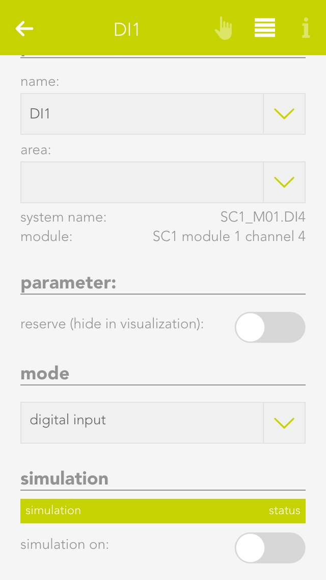
You can use a digital input for functions not provided by any evon Smart Home function module. You can name each digital input and simulate then for test purposes.
You can find the app “digital inputs” under “all apps” – “digital inputs”.
Reserve
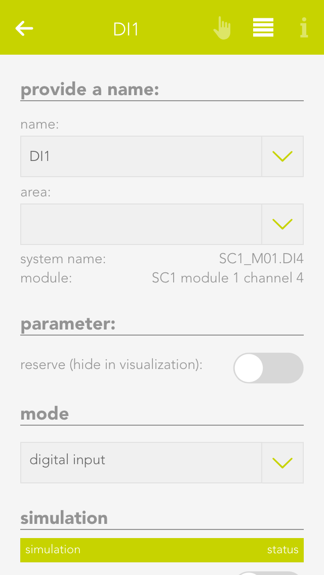
If you have a digital input in your system that you are not using, you can activate the option “reserve (hide in visualization) to hide this digital input in the app “digital inputs”. (To unhide this, the digital input can be found in the hardware app)
Mode
If you wish to change the mode, i.e. convert a digital input into a button or a movement detector, this can be done in the parameter panel for the digital input under “mode”.
If you have connected a digital input to a scene and would like to test the scene, you do not have to navigate to the digital input and activate it every time, you can change it directly via simulation. To do this, activate “simulation on” in the operator panel to see the option “simulation value” with which you can change the state. Warning, once the simulation has been activated, the autonomous function will no longer work! Any changes in the state of the input “hardware” will be overwritten by the simulation.
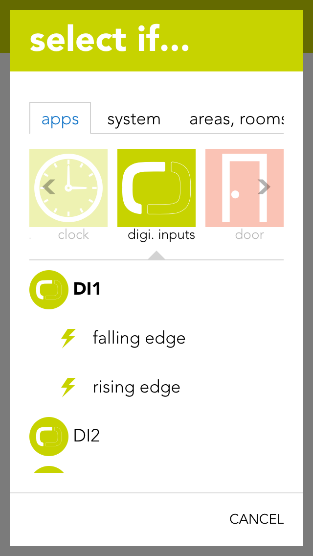
You can also use a digital input for a scene (in as far as it has been named). Select the digital input in the scene’s “IF ….” and decide whether you want the scene to be carried out on the rising or falling edge.
Rising edge
The electrical contact of the digital input has been closed.
Falling edge
The electrical contact of the digital input has been opened.
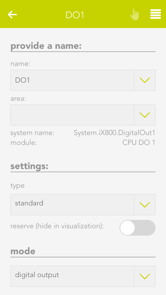
The app “digital outputs” provides you with an overview of all digital outputs in your system. This is where you can name them and change the state of the outputs.
The app “digital outputs” is located under “all apps” – “digital outputs”.
You have two possibilities to change the state of a digital output. Either you can click on the power symbol on the left in the object panel or you can click on the button “switch” in the operator panel.
You can give a name to a digital output in the parameter panel and optionally allocate it to a room.
Save output if bus fault
If the output is active when the bus connection to the CPU fails (for example if the 24V power supply to the module fails), this option lets you guarantee that the active remains activated even in a fail state. If this option is not activated, then the output is reset after every bus connection failure.
In safety-critical controllers, it should be carefully examined whether this function should be activated, since this output is kept active if the system fails.
Mode
With the mode setting, you can change the behavior of the output once it is active. The following options exist:
Standard
This ist the normal setting for a digital output. With this, the output stays active until the signal ends.
Minimum on duration
With this mode, the output stays active for at least the specified time, even when it is deactivated before.
Pulse
In this mode, the output will automatically be deactivated after the defined timeframe.
Reserve (hide in visualization)
If you have a digital output in your system that you do not use, then you can hide this digital output in the digital output app by activating the option “reserve (hide in visualization)” (located in the parameter panel). (To unhide, the digital output can be found in the hardware app).
Change mode
If you wish to change the mode, i.e. convert a digital output to a socket, then you can do this by changing the mode for the digital output in the parameter panel.
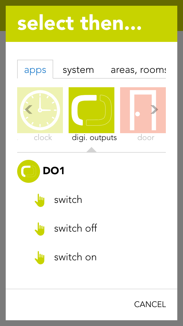
You can also use a digital output for a scene (in as far as it has been named). In the scene’s “if …” simply select the digital output to see the following possibilities:
Switch off
The digital output is switched off.
Switch on
The digital output is switched on.
switch on for
The digital output will be switched on for a defined amount of time.
Toggle
The state of the digital output is toggled.
The app “sockets” provides an overview of all sockets in your system and allows you to name them and change their state.
The app “sockets” can be found under “all apps” – “sockets”.
You have two possibilities to change the state of a socket. Either you can click on the power symbol on the left in the object panel or you can click on the button “toggle” in the operator panel.
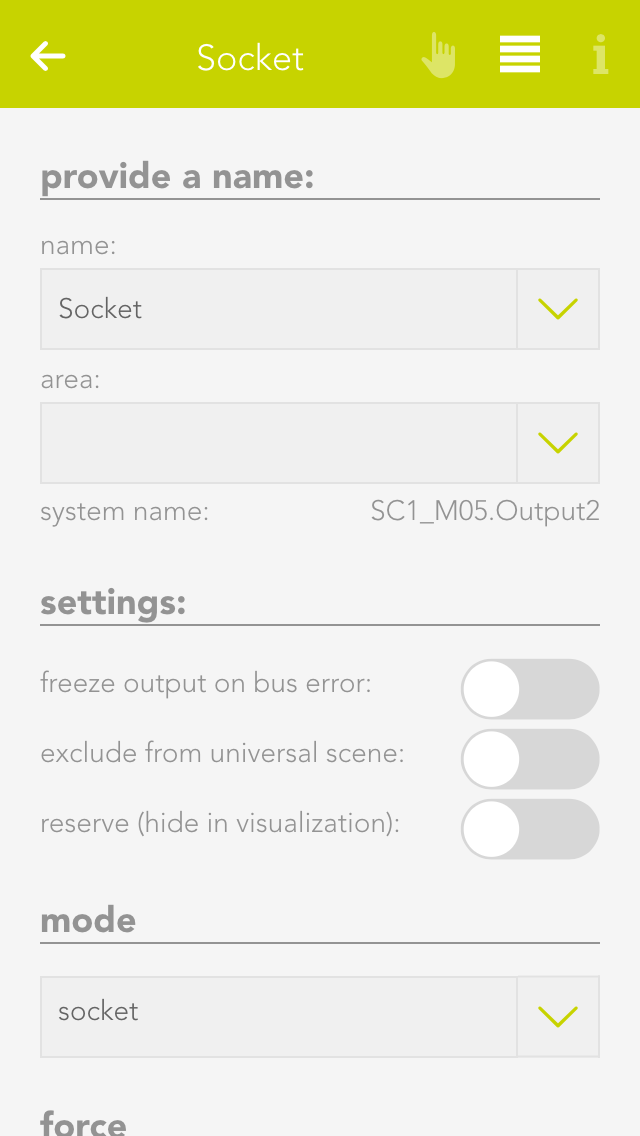
The parameter panel lets you give the socket a name and optionally allocate it to a room.
Save output if bus fault
If the socket is currently active and the bus connection to the CPU fails (e.g. the 24V power supply to the module fails), then activating this option will guarantee that the socket remains active even in a fail state. If this option is not activated, then the socket is reset after every bus connection failure.
In safety-critical controllers, it should be carefully examined whether this function should be activated, since this output is kept active if the system fails.
Reserve (hide in visualization)
If you have a socket in your system that you do not user, you can hide this socket in the app “sockets” by activating the option “reserve (hide in visualization) (located in the parameter panel). (To unhide, the socket can be found in the app “hardware”).
Change mode
If you want to change the mode, i.e. convert socket to a digital output, then this can be done by changing the mode in the socket’s parameter panel.
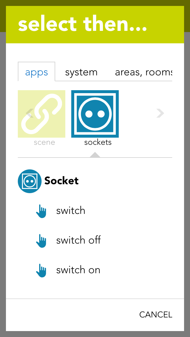
The socket can be used for a scene (in as far as it has been named). In the scene’s “if….”, select the socket and one of the following possibilities:
Switch off
The socket is switched off.
Switch on
The socket is switched on.
Switch on for
The socket is switched on for the time you define.
Toggle
The status of the socket is toggled.
An analog input can measure voltage in the range 0-10V. This voltage is then scaled to the range defined by the user. This value can be used by the user for calculations (using logic), or simply to trigger scenes if the value exceeds or falls below certain (definable) limits.
The analog inputs are located under “all apps” – “analog inputs”.
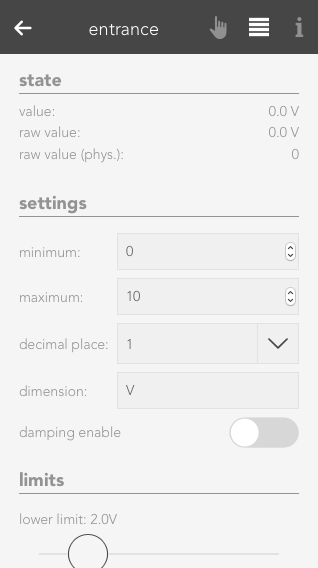
Minimum/Maximum
Minimum and maximum limits of the measured value. These inputs must be taken from the description of the sensor used. For example, you wish to measure the humidity in a room and use a sensor with a 0-10V output signal. The sensor documentation tells you that the sensor can measure humidity from 0% to 100%. The minimum limit is hence 0 and the maximum limit is 100.
Number of decimal places
Indicates the number of decimal places used to calculate the value.
Dimension
This is where you define exactly what you wish to measure with this analog input (e.g. temperature °C).
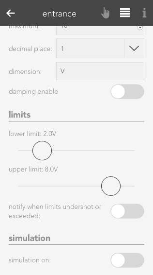
Notification on limit violation
If the value of the analog input falls below the lower limit or exceeds the upper limit, then you will be notified by the system if this checkbox is activated.
Upper limit
Enter the upper limit here. If the value exceed this limit, you can react with a scene by selecting the trigger for “value above upper limit” in the “IF …” statement.
Lower limit
Enter the lower limit here. If the value falls below this limit, you can react with a scene by selecting the trigger for “value below upper limit” in the “IF …” statement.
Der Analoge Eingang bietet folgende Auslöser für evon Smart Home Szenen (Wenn...):
Raw value
A raw value is the voltage (0-10V) measured on the input of the module.
Raw value (phys.)
Corresponds to the output of an analog/digital converter and is used for the calculation into the physical measured value.
Value
Corresponds to the scaled value resulting from the raw value, minimum and maximum.
Value = (Raw value phys. / Raw value phys. MAX) * (Maximum – Minimum) + Minimum.
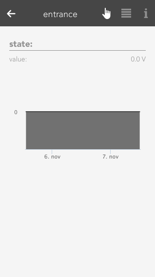
The Operatorpanel of the selected Analog Input also provides you with a chart, which keeps track of the measured values.
If you wish to simulate the value for an analog input, this is easily done by activating the option “simulation on” in the operator panel and selecting the desired value in the slider. This can be useful if you have defined a scene you wish to be carried out if a limit is exceed and you wish to test what happens.
An analog output outputs voltages in the range 0-10V. To do this, enter a value in your defined area and this will be output as a voltage between 0-10V.
The analog outputs can be found under “all apps” –“analog output”.
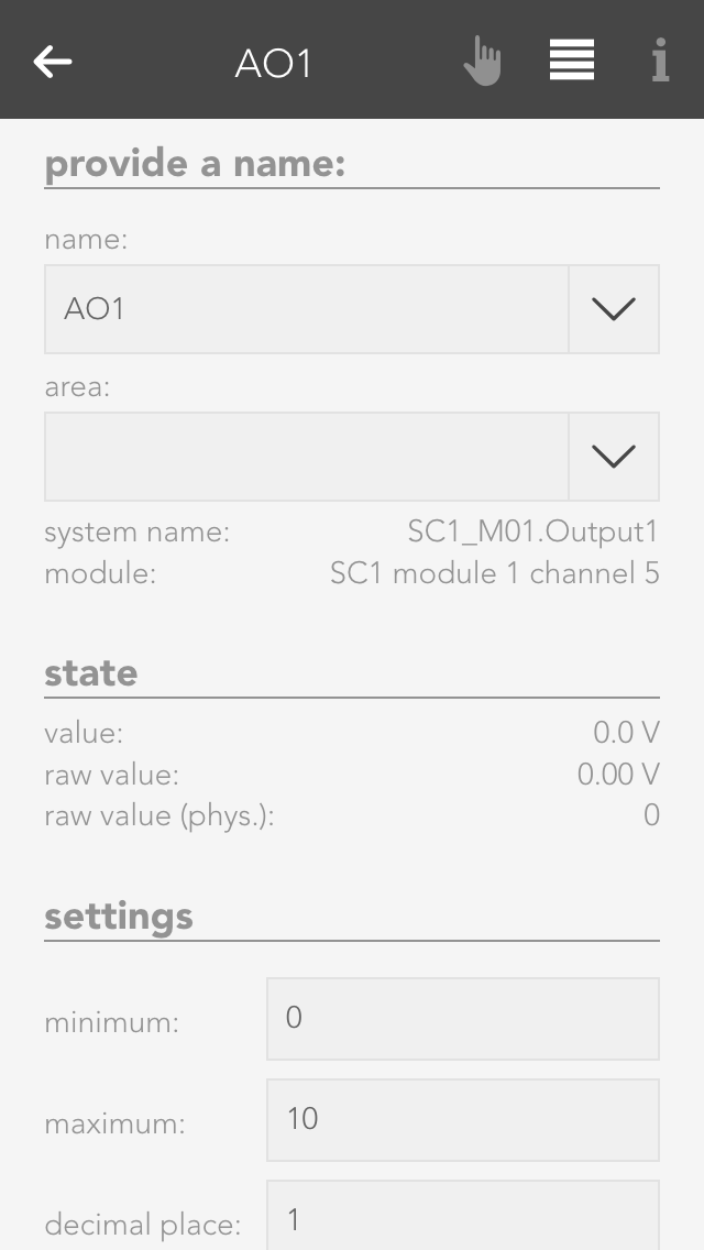
Minimum/Maximum
The calculated value is in the range between the minimum and maximum. This means that if 10V are meant to be present on the module output, then the value must be set to the defined maximum value (100%).
Number of decimal places
Defines the number of decimal places for the calculation.
Dimension
Define here what you wish to control with this analog output (e.g. speed: %)
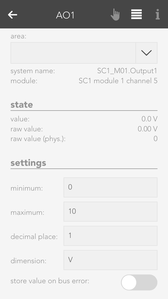
Stored value upon bus error
If the control were to fail, the last value would be stored if you have activated this option. If you did not activate this option, the value present when the control failed will be lost.
Der Analoge Ausgang bietet folgende Funktionen für evon Smart Home Szenen (Dann...):
Raw value
The raw value is the voltage 0-10 V that is present (set) on the output of the module.
Raw value (phys.)
This is the digital value sent to the module.
Value
This is the scaled value that has been converted to the defined range between minimum and maximum, with the defined number of decimal places and the defined dimension.
There are two different possibilities to set a value to the analog output. Either you set the value via the operator panel for the analog output, or you select the analog output in a scene for the “if …” statement and then select “write value”. Then you can change the value by clicking on the pencil.
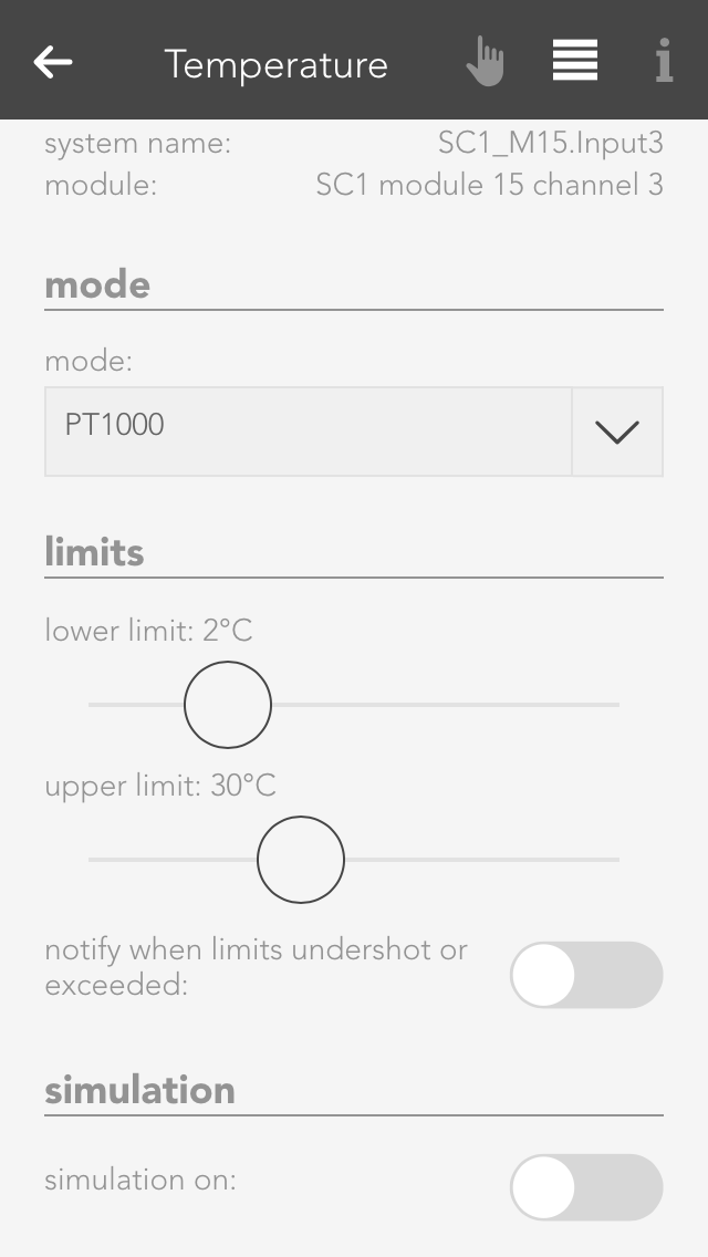
You can view all the module channels to which you can connect temperature sensors (e.g. PT1000) in the app “temperature”.
The temperature sensors can be found under “all apps” – “temperature”.
With module A1240, you can only set the temperature limits (as described in the item “scene” above). This module can only accept temperature sensors of type PT1000.
If you posses a module of type A1380, you can connect temperature sensors of type PT1000, KTY81-110 and KTY81-210. To ensure that the modules know which sensor has been connected, you must navigate to the parameter panel for this temperature sensor and select the type under “mode”.
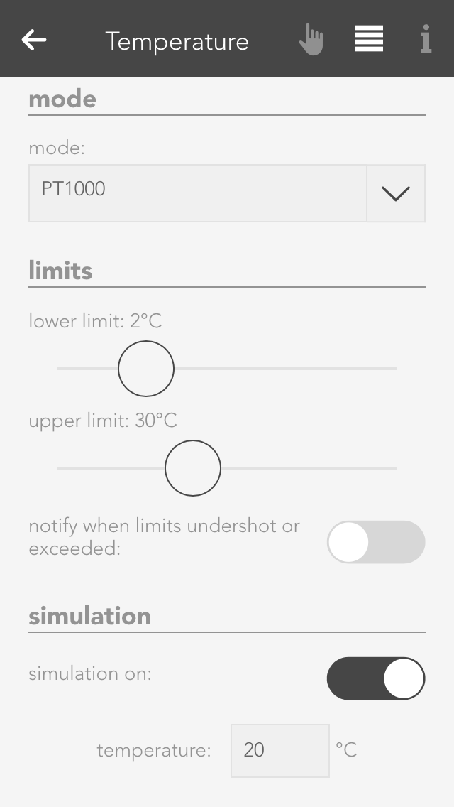
If you want to know what happens if the temperature rises above or falls below a certain value, then you don’t need to cool or heat the temperature sensor. You can use the option “simulation” in the operator panel. Simply activate the checkbox “simulation on” and enter the desired temperature in the input field that appears. Warning, do not forget to deactivate the simulation when you have finished testing.
Hier werden Dir einige Beispiele beschrieben wie Du einen Temperatursensor verwenden kannst.
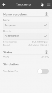
Outside temperature
If you want a temperature sensor in your system to determine the outside temperature, you need to add it using the button “add” in the global settings under the item “outside temperature” and drag it to the first position. (More information in this in the documentation for global settings).
External current value for room climate zone
If you want to use this temperature sensor as an actual value for a room climate zone, then you must set the mode to “external actual value” in the desired room climate zone under “settings” and then connect the temperature sensor with it (more detail in the chapter “room climate”).
Scene
In order to link a temperature sensor with a scene, you must first allocate a name to it. Then you can set an upper and a lower temperature limit in the parameter panel that you can use in the scene for the “if …” statement. You can create a scene for the temperature falling below the lower limit or rising above the upper limit.
Logic
If you are an expert with the app “logic”, you can also use this temperature sensor here by connecting the input of a logic element with the current temperature reading.
Die Temperatur App bietet folgende Auslöser für evon Smart Home Szenen (Wenn...):
- Obere Grenze überschritten: Das konfigurierte obere Temperaturlimit wurde überschritten
- Untere Grenze unterschritten: Das konfigurierte untere Temperaturlimit wurde unterschritten
Durch die Umwandlung von digitalen Ausgängen zu Lüfter können diese beispielsweise für die Ansteuerung von WC Lüfter verwendet werdenDiese Lüfter reagieren automatisch auf Lichter desselben Raums oder optional auf Taster oder Bewegungsmelder.
Sie finden die Lüfter unter „Alle Apps“ – „Lüftung“
Um einen Lüfter zu erstellen können Sie einen beliebigen digitalen Ausgang verwenden. Öffnen Sie dazu das Operator Panel des gewünschten digitalen Ausgangs und ändern Sie den Typ auf "Lüfter". Der digitale Ausgang wird automatisch zu einem Lüfter umgewandelt und ist unter Lüftung zu finden.
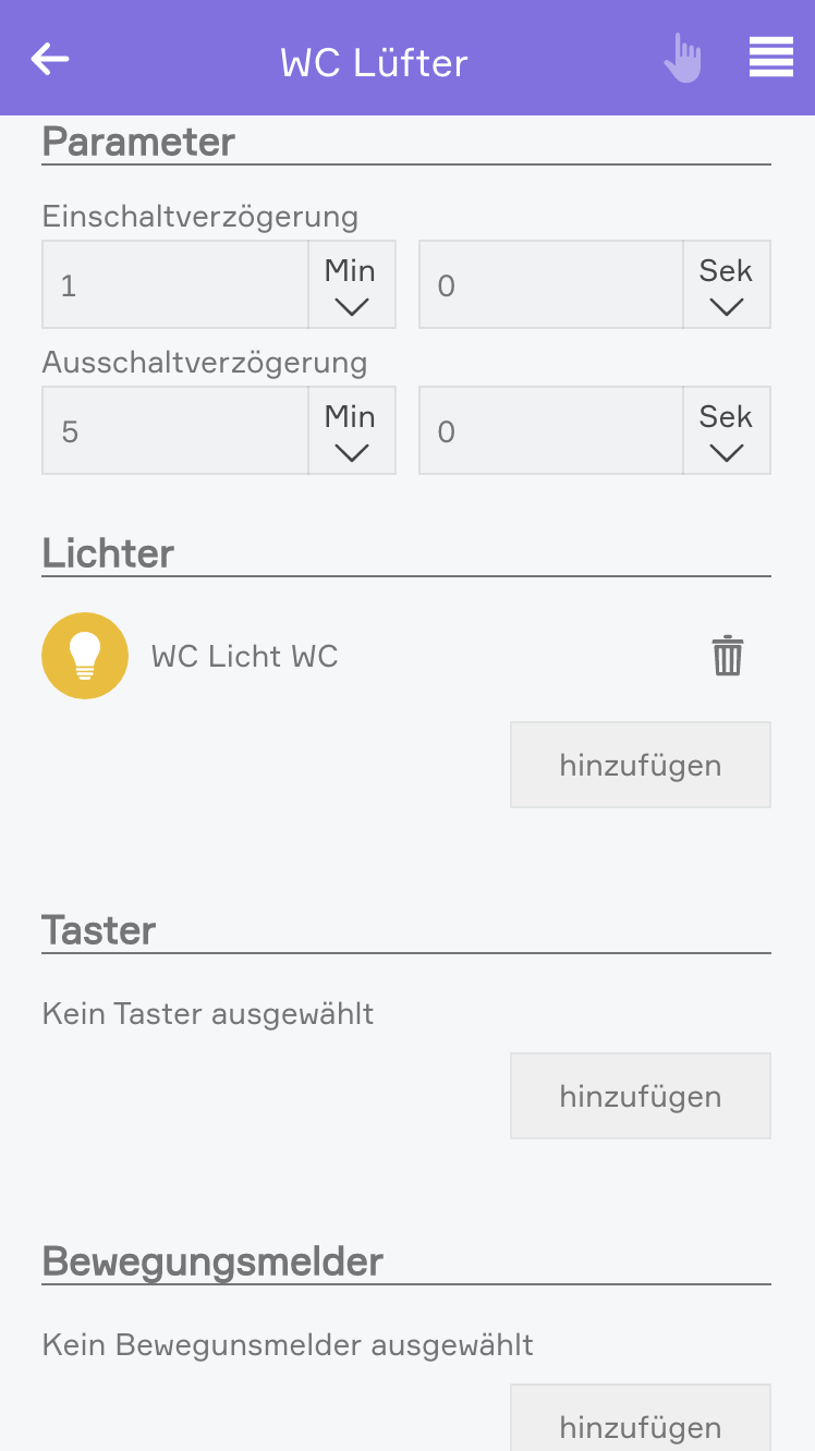
Durch das Auswählen eines Raumes werden automatisch alle im Raum befindlichen Lichter mit der Lüftung verknüpft. Sie haben jedoch jederzeit die Möglichkeit, Lichter zu entfernen oder hinzuzufügen. Zusätzlich haben Sie die Möglichkeit, Bewegungsmelder und Taster zu verknüpfen.
Einschaltverzögerung:
Beim Einschalten des ersten verknüpften Lichtes, bzw. der ersten Betätigung eines verknüpften Tasters oder der ersten Aktivierung eines verknüpften Bewegungsmelders wird die Einschaltverzögerung aktiviert. Nach Ablauf der Einschaltverzögerung wird der Lüfter eingeschaltet.
Ausschaltverzögerung:
Nach dem Ausschalten des letzten verknüpften Lichtes, bzw. der nach der letzten Betätigung eines verknüpften Tasters oder der Deaktivierung des letzten Bewegungsmelders wird die Ausschaltverzögerung aktiviert. Nach Ablauf der Ausschaltverzögerung wird der Lüfter ausgeschaltet.
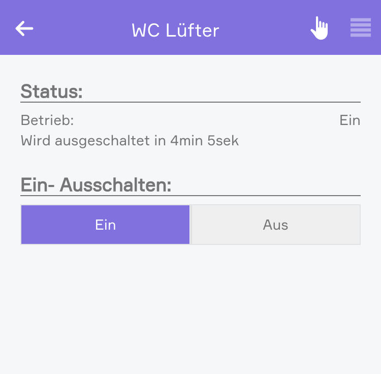
Im Operator Panel sowie im Object Panel haben Sie die Möglichkeit, den Lüfter zu steuern.
Durch das manuelle Einschalten des Lüfters wird der Lüfter sofort eingeschaltet und die Ausschaltverzögerung aktiviert. Nach Ablauf der Ausschaltverzögerung wird der Lüfter wieder ausgeschaltet.
Durch erneutes Einschalten des Lüfters, während die Ausschaltverzögerung aktiv ist, wird die Ausschaltverzögerung wieder zurückgesetzt.
Durch das manuelle Ausschalten wird der Lüfter sofort ausgeschaltet.
Der Lüfter bietet folgende Funktionen für evon Smart Home Szenen (Dann...):