Configuration
Once you have connected the evon Smart Home app with your evon Smart Home, there are just a few steps to be taken in order to adapt your evon Smart Home to your requirements.
Once you have connected the evon Smart Home app with your evon Smart Home, there are just a few steps to be taken in order to adapt your evon Smart Home to your requirements.
Use the app “areas” to organize your evon Smart Home into rooms and elements within the rooms (e.g. lights, blinds …). This way, you will be able to find them quickly.
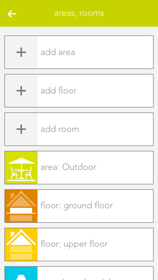
Your previously defined rooms will be displayed on the home screen (as long as they contain elements). To modify the rooms, open the “settings” app and select “areas, rooms”.
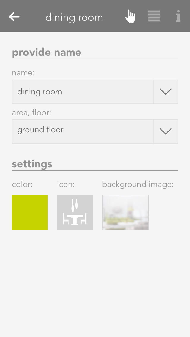
In order to add rooms, areas and floors to your evon Smart Home, simply tap on the corresponding element (e.g. “add room”). This automatically opens the operator panel for the added element. Enter the name into the field “name” and an abbreviation in the field “abbreviation” for the room. If you want to allocate this new room to a floor, simply select the floor you want. If you want to move the area back to the highest level, select the empty entry in “area, floors”.
Alternatively you can first navigate to a floor and add a room there.
If you wish to personalize your rooms, you can select colour, icon and background picture for your room. Do this by opening the operator panel for the room via in “settings” – “areas, rooms” and select the element under “settings” and modify it.
Open the area via the button “edit” and view the elements for this area. If you want a shortcut to an area, simply click on the area of the symbol in the object panel (left).
You can also link each room with a room thermostat. Do this by allocating an element to this room in the app room climate. If you have allocated more than one room thermostat to a room, you can use the parameter panel of the room to select the room thermostat you wish to use for the room temperature display.
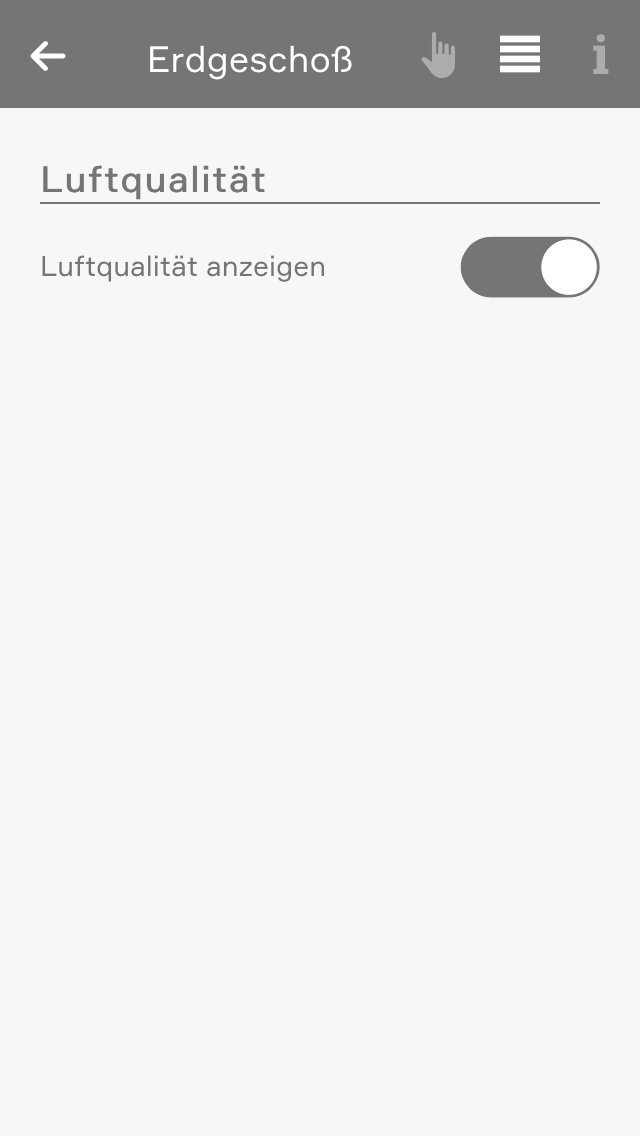
In den erweiterten Einstellungen können Sie angeben welche Elemente zur Berechnung und Anzeige des Raumklimas verwendet werden sollen. Außerdem können Sie hier das Raumklima des Raumes ausblenden.
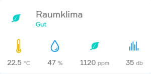
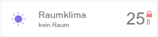
Wenn Temperatur-, CO2-, Feuchtigkeits- oder Geräuschsensoren dem Raum zugewiesen wurden, wird im Raum das Raumklima angezeigt.
Je nach Zustand des Raumes wird hier ein Gesundheitswert berechnet welcher von "Hervorragend" bis "Sehr schlecht" reicht. Wenn sich der Zustand des Raumes verschlechtert bekommen Sie eine Benachrichtigung über den verschlechterten Zustand.
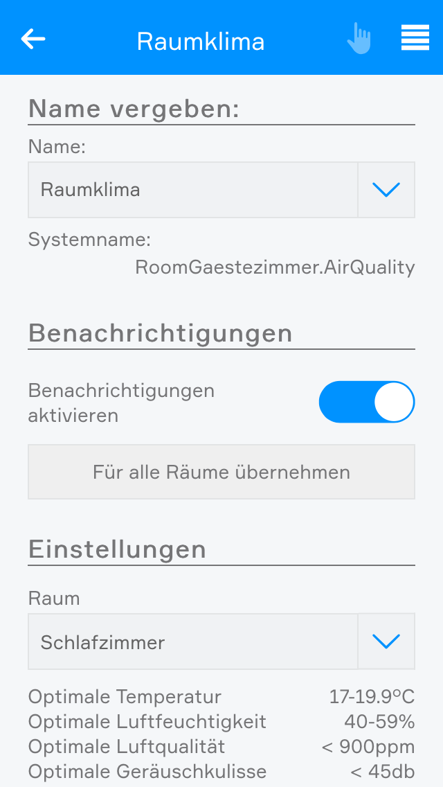
In den Einstellungen des Raumklimas können Sie die Benachrichtigungen deaktivieren.
Außerdem können Sie hier die optimalen Grenzwerte des Raumes anpassen.
After you have connected via the evon Smart Home app to your evon Smart Home system, you should name all of the connected devices (lights, blinds, heating circuits, etc.) and allocate them to a room. This helps you to not only find and operate them easier, but also to access further functions.
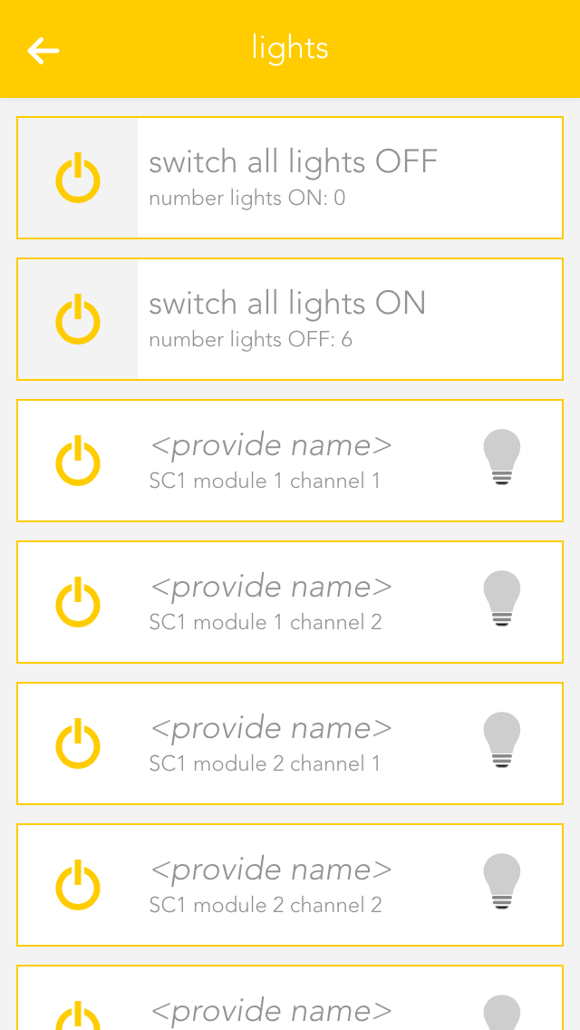
Open “lights”, “blinds” or “room climate”, depending on the items you wish to modify the names and rooms.
The app shows you a list of central functions and below that a list of your elements – this corresponds to the channels of your evon Smart Home modules. More detail concerning the central functions can be found in the corresponding documentation.
Tap on the area that displays the name and the room, in this case “ no name”, “no room” to open the settings for this device.
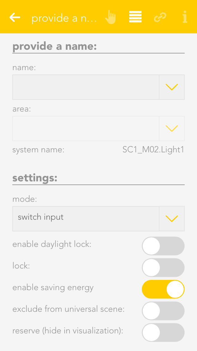
Enter the name of the device in the field “name”. You can type any name in here, or use a predefined name by tapping on the small arrow.
Tap on the field to select a room. The system already has a predefined few names that you can use. If you cannot find a suitable room in the list, create one in the settings -> areas and custom rooms.
You do not need to specifically save your changes, simply tap on the arrow symbol in the menu bar.
Choose a distinctive name depending on the device and purpose like: ceiling light, ambient, radiator or wall heating.
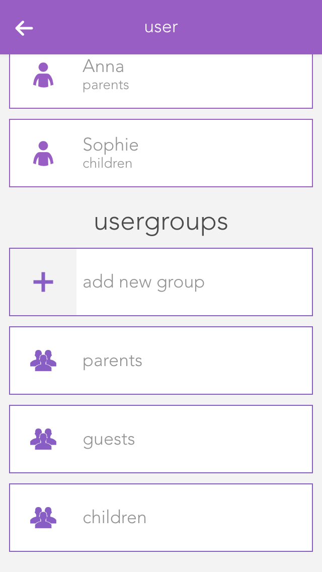
You can allocate different rights in your evon Smart Home to users, for example so that children can only use functions in the children’s room. The rights are controlled via the user groups.
You can find users and user groups in “all apps” – “settings”.
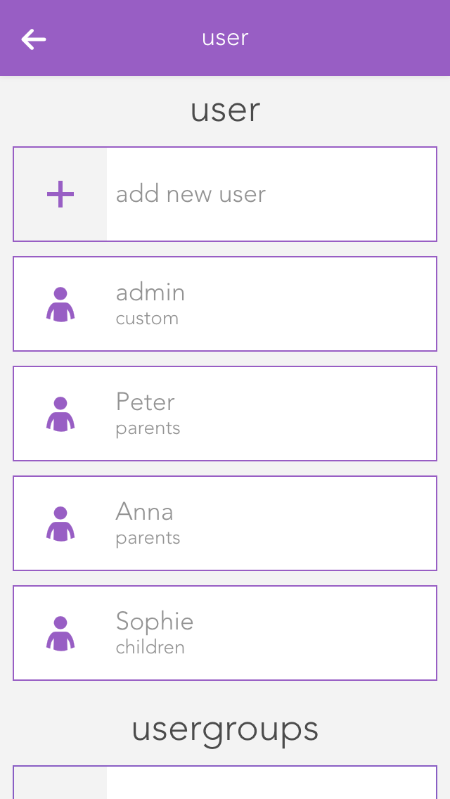
A user allows you to control exactly the rights for your evon Smart Home.
You can add a new user here or configure an existing one. To add a new user, simply select “add user”. This opens a panel where you can enter the user name and an optional description. Enter a password for the user so that you can login using the username.
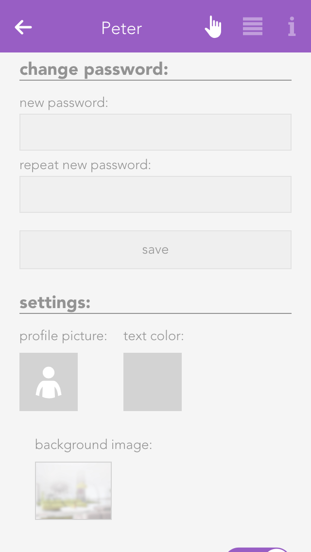
Profile picture
The profile picture to be displayed for this user.
Background picture and text colour
You change the background of your visualization as you wish. The text colour selects the colour of titles such as “favourites” on the home screen so that they are readable, even with other background pictures.
Show areas on the home screen
This setting lets you define whether areas will be displayed on this user’s home screen.
Own favourites
If you activate the option “own favourites”, you can customize the favourites on your own home screen without these changes being visible to other users. If this option is deactivated, then your favourites are shared with other users and any changes will be visible to all users.
Language
This lets you change the language for this user. To change the language of the current user, click on “load new language settings”.
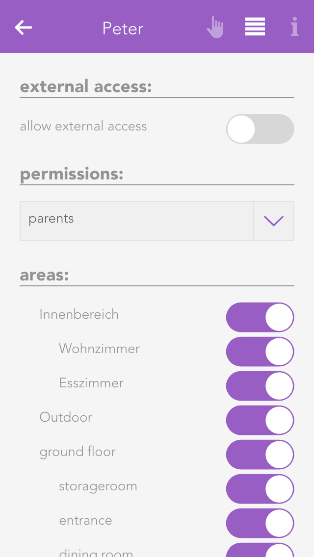
Permit external access
The option “allow external access” lets you decide whether this user is permitted to connect to your evon Smart Home externally.
Rights
This allows you to allocate rights to this user. If you want to allocate rights independently from a group, simply select “user defined”. The individual rights are explained further down the screen. If the user is to have no rights, simply select “no rights”.
Areas
The section “areas” lets you select which the areas this user is to have access to. If you have allocated this user to a user group, the rights in this group have already been defined for this area and hence you only have the possibility to limit the rights for individual areas further.
Some changes cannot be made to the user you have used for your login. So for example you cannot withdraw administrator rights or delete the current user.
User groups allow you to configure rights for several users.
The settings can be modified for a user group that already exists, or a new one can be created. To create a new user group, click on the element “add group”. This opens a panel where you can enter the name of the group (e.g. “guests”), and assign colour and an icon.
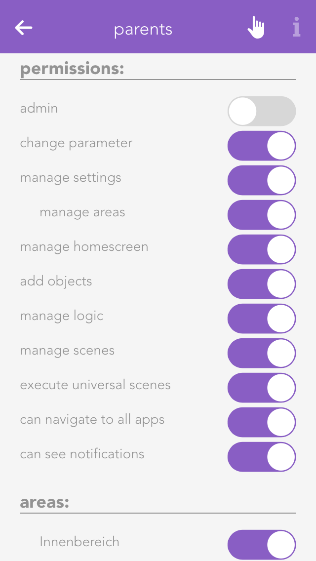
Rights are used to limit what a user in this group is allowed to do in your evon Smart Home.
Admin
This level of rights gives the user full access to all possibilities in the system. All the following rights are deactivated, since they are all included in the admin rights.
Change parameter
Users in this group are allowed to change parameters, i.e. all settings accessible via the parameter symbol.
Manage settings
The user can open the settings (all apps – settings) and make changes. Exceptions are the user settings.
Manage home screen
The user can change the start page of the app, in other words, they can set favourites and move elements. See also “own home screen”.
Add object
The user can add new objects to the system, for example a new surveillance camera, a new Denon system, etc.
Edit logic
The user can create and edit logic elements.
Edit scenes
The user can create and edit scenes; otherwise scenes can only be executed.
Edit area
The user can create and edit areas.
Execute universal scene
The user can execute universal scenes such as close all blinds, switch on all lights, etc.
See all apps
The user can open all apps, otherwise they only have the possibility to open apps that are on the home screen.
See notifications
Notifications are displayed for the user (such as wind, alarm system, etc.).
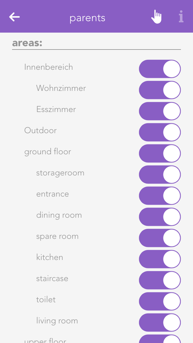
In “areas”, you can define which areas the users in the group will be able to access.
A light in evon Smart Home corresponds to a lighting channel that is connected to an evon Smart Home light module. Once connected, each light can be switched on and off. In addition, you also have the pre-defined universal functions “all lights on” and “all lights off”.
You can find the lights under “all apps”.
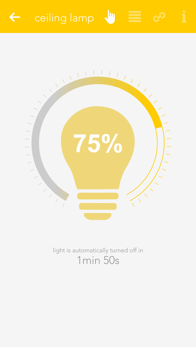
You can switch a light on or off via the “power symbol” on the left side. The right-hand side of the panel shows you whether the light is currently switched on or off. Clicking on the element takes you into the extended operation or configuration of this light. You can switch the light on or off by clicking on the bulb symbol.
If you have a dimmable light, you can switch in on or off via the object panel. Of course, you can also control this dimmable light via the operator panel by setting the circular slider around the light to the desired value.
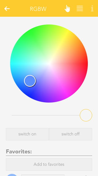
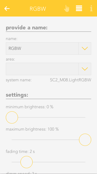
RGBW
If you own a RGBW Module (HC-L1644), you can control the desired light color and brightness from within the OperatorPanel.
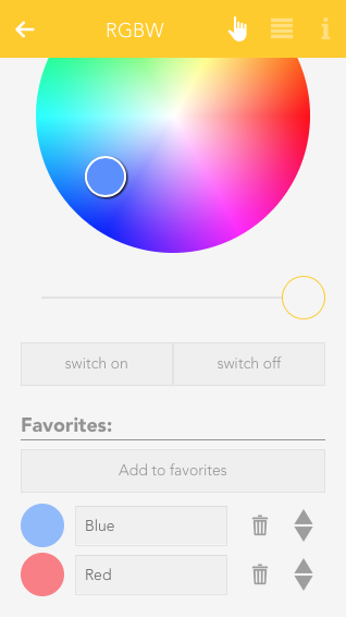
Additionally, you can also save the current light settings as a favorite and activate it again later.
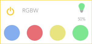
Saved favorites will also be displayed in the ObjectPanel, if you resize it to the appropriate size.
Once a light has been given a name, you can configure it to suit your needs.
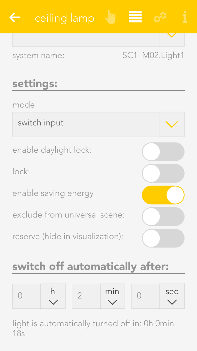
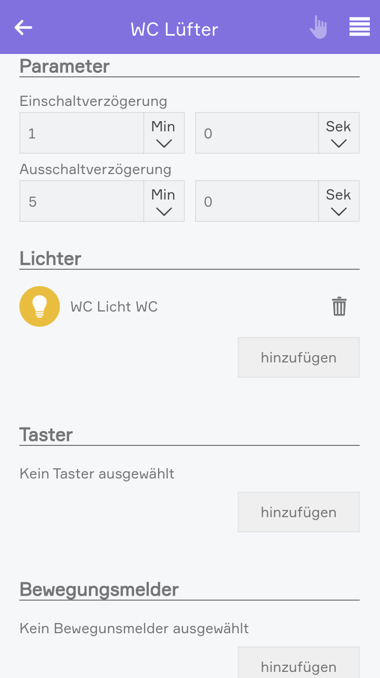
Mode
This setting determines whether this light is controlled by a switch or a presence detector. If you select “presence detector”, the settings to adjust the time the light is switched on are displayed.
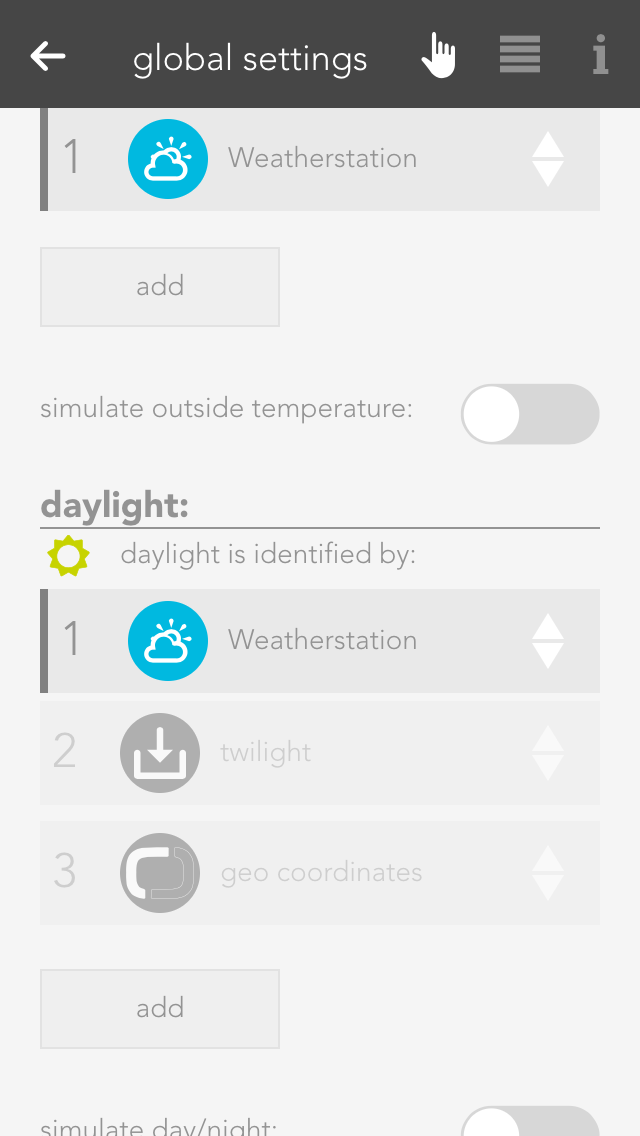
Activate daylight lock
This option lets you prevent the light from switching on during the day (if there is sufficient light). This can be used for a hallway where the light is controlled by a presence detector. You can adjust the source for daylight detection in the global settings.
Lock
If you activate “lock”, then the light cannot be switched on or off by the switch, nor by the presence detector.
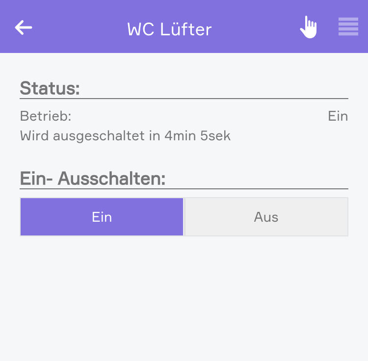
Activate energy saving mode
This option lets you configure the light to switch itself off after a certain time. If you have activated this option, then the software shows you the settings for the time the light is to remain switched on. You can change this time to anything you want.
Remove from universal scene
An example of a universal scene is “all lights off”, where all lights are switched off. However, if you want a particular light to be excepted from this, then activate this option (useful for lighting an aquarium).
Reserve
If you have a module with spare connections, i.e. where no light is connected, the app still shows that the light is on or off, because the output is active (although no light is actually connected). The “reserve” field lets you hide lights that are not used/connected. You can reactivate this light via the corresponding module in the app “hardware”.
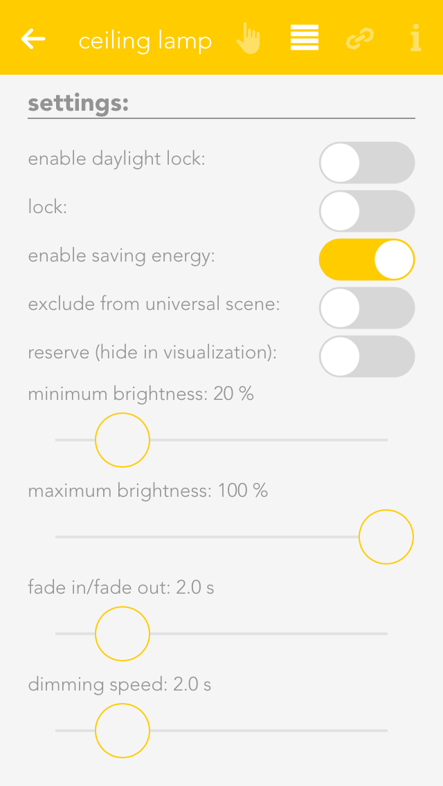
Minimum and maximum brightness
Minimum and maximum brightness: many lights only have a noticeable change in brightness within a certain range. Hence you can set a minimum and maximum brightness level so that dimming will happen in between those limits. The visualization will still display 0% to 100%.
Fade in time
This is the time that the light is to take to reach the desired brightness from being switched off.
Dim speed
This is how fast the brightness is reached when the button is pressed continuously.
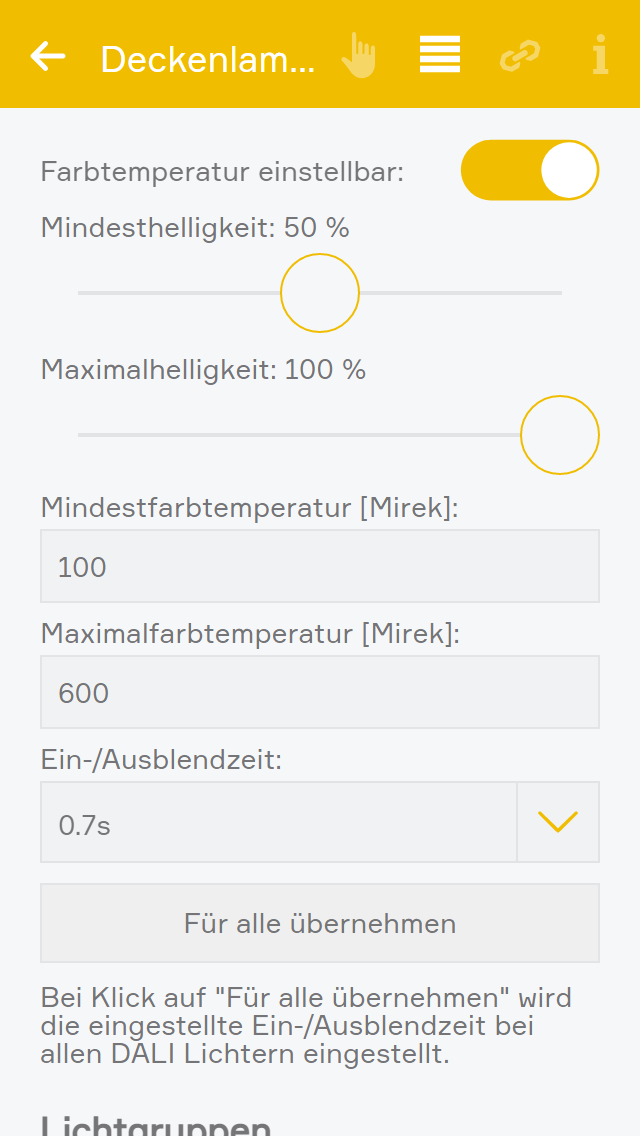
Diese Einstellungen gelten nur für Dali Leuchten, welche eine Warmweiß/Kaltweiß Steuerung ermöglichen.
Farbtemperatur einstellbar
Zeigt den Slider zum Einstellen der Farbtemperatur in der Bedienung an.
Mindestfarbtemperatur
Entspricht dem Mindestwert in Mirek welcher auf der Leuchte gesetzt werden kann. Dieser Wert kann aus dem Datenblatt der Leuchte entnommen werden und kann einen Wert zwischen 1 und 65534 haben.
Maximalfarbtemperatur
Entspricht dem Maximalwert in Mirek welcher auf der Leuchte gesetzt werden kann. Dieser Wert kann aus dem Datenblatt der Leuchte entnommen werden und kann einen Wert zwischen 1 und 65534 haben.
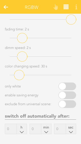
Minimum brightness
Legt die kleinste Helligkeitsstufe fest
Set the minimum brightness level
Maximum brightness
Set the maximum brightness level
Fading time
This will set the time it takes for the light to dimm between "on" and "off" state rather than switching instantly.
Dimm speed
Sets the time it takes for the light to dimm to the desired brightness.
Color changing speed
This setting will affect how fast the light switches through all available colors when using the linked switch with a longpress.
Only white
When this setting is active, the color wheel will be hidden and only the brightness slider is available in the OperatorPanel.
Enable saving energy
Enables the energy saving mode, in which the light will switch itself off after a given time. You can adjust the desired time with the given interface elements, which appear once this setting is active.
Exclude from universal scene
Activating this option will exclude it from Universal scenes which will not impact this light anymore until this option is turned off.
Switch off automatically after
This option only appears after the "enable saving energy" setting it active. It allows you to adjust the time it takes for the light to switch itself off.
While the standard mode of the RGBW Module is "1xRGBW" it is also possible to switch to "4xWhite". This will allow you to connect 4 separate lights to one RGBW module and use them like normal dimmable lights. To change this setting, go to "All apps" - "Hardware" and navigate to the correct module ("Light1644"). Click on the Name and change the setting in the appearing OperatorPanel.
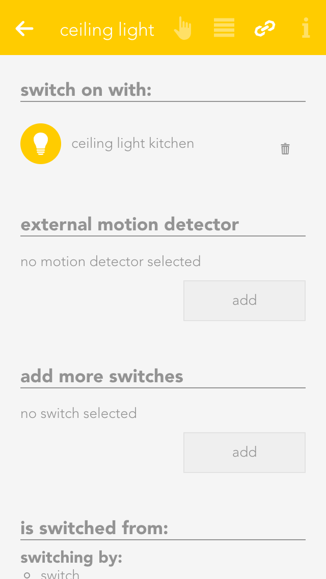
Linking allows you to connect your light to other elements in your evon Smart Home.
Switch on with
If you want this light to be switched on as soon as another is switched on, then use the function “switch on with”. The button “select” lets you select the other light you wish to link to this one.
Bewegungsmelder/Taster hinzufügen
Further presence detectors or buttons can be defined in one light channel to control the light.
The function of the linked button or presence detector depends on the autonomous light function, i.e. whether the button or presence detector mode has been selected.
Über die Gruppenfunktion lassen sich mehrere Lichter zu einer Gruppe zusammenfassen. Dadurch werden alle gleichzeitig geschalten.
Um eine neue Lichtgruppe anzulegen, wählen Sie "Neue Lichtgruppe" innerhalb der Licht App.
Eine neue Lichtgruppe wird erstellt.
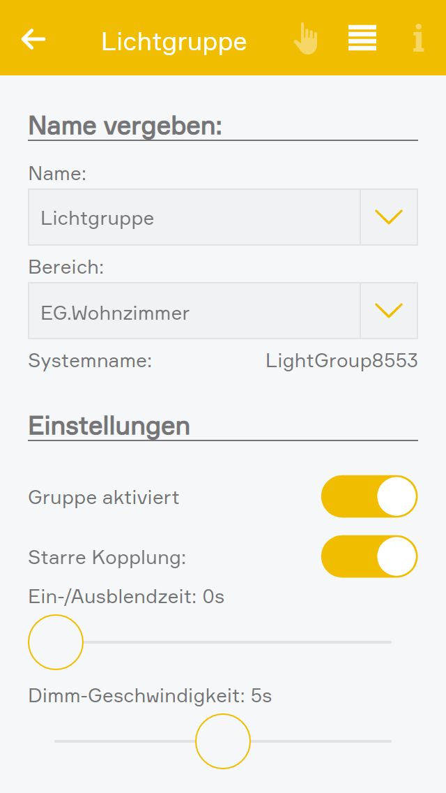
In den Einstellungen der Gruppe sollten Sie als erstes einen Namen vergeben und einen Raum zuordnen.
Hier haben Sie außerdem die Möglichkeit, die Gruppe zu deaktivieren. Dadurch können Sie eine bereits konfigurierte Gruppe temporär abschalten, ohne sie löschen zu müssen.
Für erweiterte Anwendungen ist das Deaktivieren der Lichtgruppe auch über die Logik möglich.
Bei einer starren Kopplung schalten immer alle Lichter gemeinsam, auch wenn der zugehörige Taster eines Lichtes betätigt wurde. Wenn die starre Kopplung deaktiviert wird (lose Kopplung), schalten die zu einem Licht gehörigen Taster nur mehr das einzelne Licht und nur die Taster welche in der Lichtgruppe definiert wurden schalten alle Lichter Gruppe gemeinsam.
Zusätzlich kann die Ein-/Ausblendezeit und die Dimm-Geschwindigkeit für die verbundenen dimmbaren Lichter gesetzt werden. Sobald dimmbare Lichter mit der Lichtgruppe verbunden wurden, wird die Ein-/Ausblendezeit und die Dimm-Geschwindigkeit von der Lichtgruppe übernommen und kann in den einzelnen Lichtern nicht mehr verändert werden.
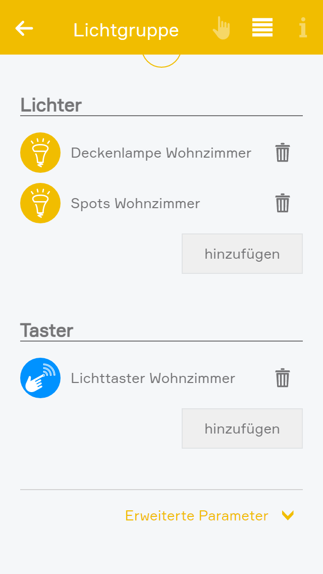
Fügen Sie nun mehrere Lichter hinzu. Alle Lichter die sich in der Gruppe befinden werden nun gleichzeitig geschalten. Schalten Sie ein Licht der Gruppe aus, werden auch alle anderen ausgeschalten. Handelt es sich bei einem der Lichter um einen Dimmer, so wechselt dieser zwischen "Aus" bzw. der zuletzt eingestellten Dimmstufe.
Die Gruppenfunktion wirkt sich sowohl auf die Bedienung über die evon Smart Home Visualisierung, als auch Taster und Bewegungsmelder aus. Sie können außerdem zu jeder Gruppe weitere Taster hinzufügen.
Sobald ein Licht mit einer Lichtgruppe verbunden wurde, werden die externen Taster des Lichtes gelöscht und die externen Taster der Lichtgruppe übernommen.
Wenn ein Taster kurz gedrückt wird, wird der Status der Lichter umgeschaltet. Wenn der Taster lange gedrückt wird, und dimmbare Lichter verknüpft sind, werden diese auf/ab gedimmt. Nach dem Loslassen und erneutem langen Tastendruck wird in die entgegengesetzte Richtung gedimmt.
Dabei verhalten sich alle Taster gleich, egal ob die Autark Taster der verknüpften Lichter oder die externen Taster. Sollten sowohl dimmbare als auch nicht dimmbare Lichter in einer Gruppe verknüpft worden sein, so schalten sich bei langem Tastendruck eines nicht dimmbaren Lichtes diese ein. Die Dimmbaren dimmen so lange auf/ab wie gedrückt wird.
Im Regelfall können Lichter und Taster nur zu einer Lichtgruppe hinzugefügt werden. Für Spezialanwendungen ist es jedoch möglich, bereits verknüpfte Lichter und Taster zu einer Lichtgruppe hinzuzufügen. Dies können Sie im Parameter Panel unter "Erweiterte Parameter" konfigurieren.
Achtung: Lichter und Taster mit mehreren Lichtgruppen zu verknüpfen ist nur dann sinnvoll, wenn immer nur eine Lichtgruppe aktiviert ist. Beispielanwendungen hierfür sind Räume, welche über Trennwände aufgeteilt werden. Hier kann es sinnvoll sein, dass Lichtgruppen je nach geschlossener oder geöffneter Trennwand deaktiviert werden.
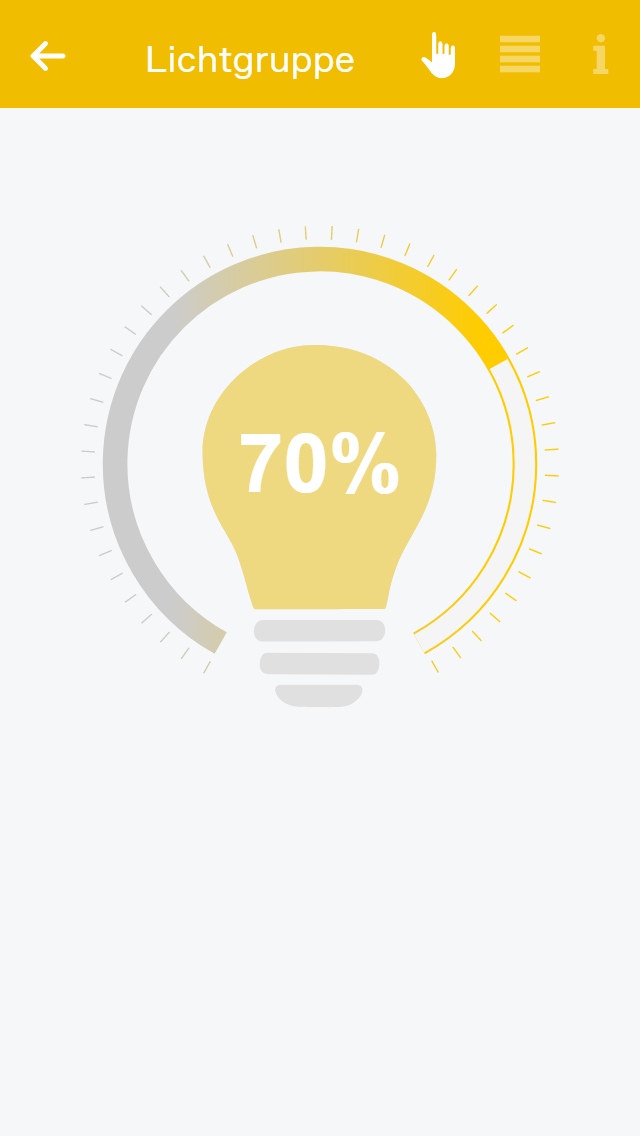
In der Gruppe können alle verbunden Lichter gesteuert werden. Wenn nur nicht dimmbare Lichter verbunden wurden, können diese über das Operator Panel ein- bzw. ausgeschalten werden. Sobald ein dimmbares Licht hinzugefügt wird steht auch das Bedienelement zum Anpassen der Helligkeit zur Verfügung, hier werden dann nicht dimmbare Lichter nur ein- bzw. ausgeschalten und dimmbare Lichter gedimmt. Sobald ein RGBW Licht verbunden ist, wird zusätzlich der Farbkreis zur Auswahl angezeigt. Dimmbare Lichter werden dann mitgedimmt und alle Lichter entsprechend Ein- bzw. Ausgeschalten. Außerdem können für RGBW Lichtgruppen Favoriten erstellt werden.
Lichtgruppen in Szenen
Lichtgruppen bieten folgende Auslöser für evon Smart Home Szenen (Wenn...):
Lichtgruppen bieten folgende Funktionen für evon Smart Home Szenen (Dann...):
If a light channel is connected to the input of a presence detector, then this light will always be automatically switched off after the defined time independently of whether an additional button or presence detector is switched on.
A presence detector light can be immediately manually switched off using an additional button.
If the time for the presence detector is to be used, then the time for the light must be set to 0. If the time for the light is to used, then the time for the presence detector must be set to 0.
Additional buttons
The light can be switched off at any time with an additional button linked to this light channel (or on, if required). If the light is switched on via the button, it is also switched off after the defined period of time.
Note that in this case, the energy saving time cannot be 0, because otherwise the button input would be immediately switched off – and hence not seem to work.
Additional presence detector
An additional presence detector can also switch the light off after the defined period of time.
Note that in this case, if the energy saving time is defined with 0, then the on/off times for the light will vary due to the times defined by the presence detector.
If a light channel input is connected to a button, this light will be switched by every linked button or presence detector according to the autonomous function.
If no automatic switch-off time is defined (energy saving mode), then the presence detector can only switch the light on.
Additional button
The light can be switched on or off at any time using an additional button linked to this light channel.
Note that in this case, the energy saving time cannot be defined as 0, as otherwise the light would be switched off immediately after the button press – and therefore not seem to work.
Additional presence detector
An additional presence detector will always switch the light on and switch it off after the defined period of time.
You can configure settings that affect all lights in “all apps – settings – lights”.
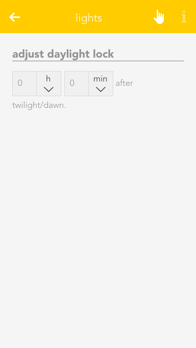
Daylight-lock-delayed switching
To configure the daylight lock, navigate to settings and select lights. You can adjust how many minutes after dusk you want the daylight lock to be deactivated and how many minutes after dawn you wish the daylight lock to be activated. In other words, if your evon Smart Home registers dusk at 8pm and you have set 10 minutes, then the daylight lock will be deactivated at 8:10pm.
Lichter bieten folgende Auslöser für evon Smart Home Szenen (Wenn...):
- Licht wurde ausgeschaltet: Das Licht wurde ausgeschaltet
- Licht wurde eingeschaltet: Das Licht wurde eingeschaltet
Lichter bieten folgende Funktionen für evon Smart Home Szenen (Dann...):
- Alle ausschalten: Alle Lichter werden ausgeschaltet
- Alle einschalten: Alle Lichter werden eingeschaltet
- auf Dauerhaft-EIN Betrieb stellen: Das Licht wird dauerhaft eingeschalten
- Auf Modus nur Weiß umschalten: Das RGBW Licht wird auf den Modus zur Weiß-Steuerung umgeschaltet
- Auf Modus RGBW umschalten: Das RGBW Licht wird auf den Modus zur RGBW-Steuerung umgeschaltet
- auf Normal Betrieb stellen: Das Licht kann wieder normal ein- und ausgeschalten werden
- Ausschalten: Das Licht wird ausgeschaltet
- Blinken: Das Licht beginnt zu blinken
- Blinken beenden: Das Licht stoppt zu blinken
- Dimmen: Das Licht wird gedimmt (nur dimmbare Lichter)
- Einschalten: Das Licht wird eingeschaltet
- Einschalten für: Das Licht wird für eine frei wählbare Zeit eingeschaltet
- Farbduchlauf starten: Das RGBW Licht durchläuft alle Farben
- Farbduchlauf starten für: Das RGBW Licht durchläuft alle Farben über den gewählten Zeitraum
- Farbduchlauf stoppen: Das RGBW Licht stoppt den Farbdurchlauf
- Favoritenfarbe aktivieren: Das RGBW Licht schaltet auf die Favoritenfarbe
- Farbe setzen über RGBW: Das RGBW Licht übernimmt die eingegebenen Werte und verändert die Farbe gegebenenfalls (nur RGBW Lichter)
- Farbe setzen über X und Y: Das Licht übernimmt die eingegebenen Werte und verändert die Farbe gegebenenfalls (nur gewisse Dali-Lichter)
- Sperren: Das Licht wird gesperrt
- Umschalten: Das Licht wird umgeschaltet
- Zu nächstem Favorit springen: Falls vorhanden wird zum nächsten Favorit gewechselt (nur RGBW Lichter)
- Farbtemperatur setzen: Die Farbe des Lichts wird umgeschaltet (nur Philips Hue White ambiance)
Das evon Smart Home DALI Modul ermöglicht Ihnen die komfortable Steuerung von DALI Lampen mit Ihrem evon Smart Home System.
Mit dem Modul L1842 können Sie zwei DALI Linien mit jeweils bis zu 16 Lichter steuern.
Mit dem Modul L1942 können Sie zwei DALI Linien mit jeweils bis zu 32 Lichter steuern.
Beachten Sie, dass bei dem Modul L1942 ein externes DALI Netzteil erforderlich ist.
Nähere Information zur Verkabelung der DALI Linien finden Sie im mitgelieferten Datenblatt des Moduls.
Bitte beachten Sie, dass nur DALI Lampen und Vorschaltgeräte unterstützt werden, welche nach dem DALI Standard IEC 62386 genormt sind.
Sie finden Ihre DALI Module unter "Alle Apps" - "Hardware"
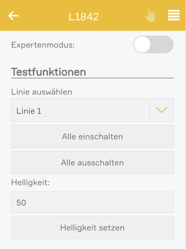
Im Parameter Panel können Sie entscheiden, ob Sie den Expertenmodus verwenden möchten.
Standardmodus: Alle Lichter auf einer DALI Linien können gemeinsam geschalten werden. Zusätzlich werden die Lichter der Linien mit den Taster der Kanäle 1 und 2 geschaltet.
Expertenmodus: Der Expertenmodus erlaubt die Steuerung jeder einzeln angeschlossenen Lampe. Hierfür müssen alle angeschlossenen Lampen adressiert werden. Die Taster der Kanäle 1 und 2 werden nicht für die Steuerung der Lampen verwendet.
Zusätzlich haben Sie im Parameter Panel die Möglichkeit, die Steuerungsbefehle Ein, Aus und Dimmen auf eine DALI Linie auszuführen.
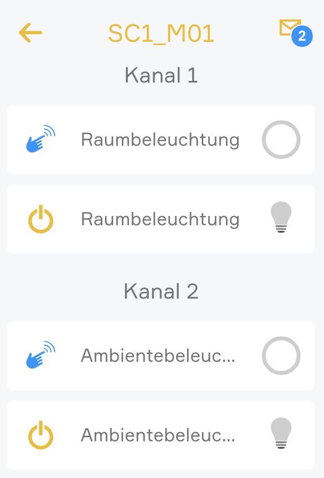
Durch Klick auf den linken Bereich des Object Panels oder durch Klick im Operator Panel auf "Kanäle anzeigen" werden alle Taster und Lichter des Moduls aufgelistet. In der Standardkonfiguration werden hier 2 Lichter aufgelistet, welche jeweils die Lampen einer DALI Linien repräsentieren.
Mit dem Expertenmodus können Sie alle angeschlossen Lichter adressieren und in weiterer Folge getrennt steuern. Beim Adressieren wird jeder angeschlossenen Lampe eine pro Linie eindeutige Adresse zugeordnet.
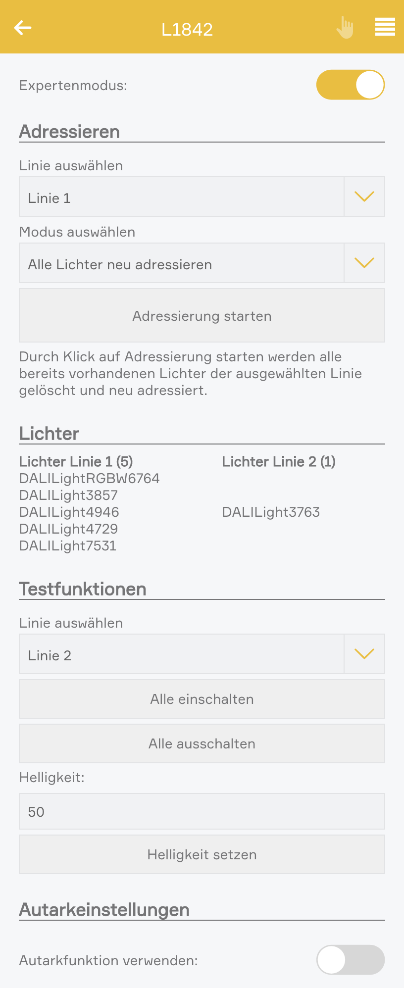
Zum Aktivieren des Expertenmodus, klicken Sie im Parameter Panel auf "Expertenmodus".
Nach der Aktivierung werden die 2 Lichter, welche die gesamten Linien repräsentierten, entfernt. Zusätzlich wird die Autarkfunktion der Taster deaktiviert und können beliebig verwendet werden. Zusätzlich erhalten Sie im Parameter Panel die Werkzeuge zum Adressieren der Lichter.
Zum Adressieren wählen Sie als Erstes die gewünschte Linie aus und anschließen den Adressierungsmodus.
Durch Klick auf "Adressierung starten" werden die Adressen unter den angeschlossenen Lampen ausgehandelt und anschließend in Ihrem evon Smart Home aufgelistet.
Adressierungsmodus "Alle Lichter neu adressieren":
In diesem Modus werden vorhandene Lichter gelöscht und alle Lichter neu adressiert.
Adressierungsmodus "Neue Lichter adressieren":
In diesem Modus werden nur neue Lichter hinzugefügt, welche noch nie adressiert wurden. Vorhandene Lichter bleiben erhalten
Auch im Expertenmodus kann die Autarkbedienung mittels der Taster des Moduls verwendet werden. Wird die Autarkfunktion aktiviert, werden mit den Tastern die Lichter der ganzen DALI Linie geschaltet.
Nach der Adressierung werden alle gefundenen Lampen unter den Kanälen des Moduls angezeigt. Sie finden die Kanäle durch Klick auf den linken Bereich des Moduls oder durch Klick auf "Kanäle anzeigen" im Operator Panel
Zusätzlich werden alle Lichter unter "Alle Apps" - "Lichter" aufgelistet und können wie gewohnt verwendet und in Szenen oder Lichtgruppen verknüpft werden.
Lampentausch:
Falls Sie eine Lampe tauschen müssen, muss diese wieder neu adressiert werden.
Mit Hilfe der Funktion "Lampentausch" im Parameter Panel wird Ihre neu verbaute Lampe automatisch adressiert.
Alle Szenen und Verknüpfungen in Ihrem evon Smart Home bleiben erhalten.
Falls Sie immer alle Lichter einer Linie gemeinsam schalten möchten, empfiehlt es sich den Expertenmodus zu deaktivieren. Das Schaltverhalten ist dann wesentlich synchroner als durch das verknüpfen aller einzelnen Lichter.
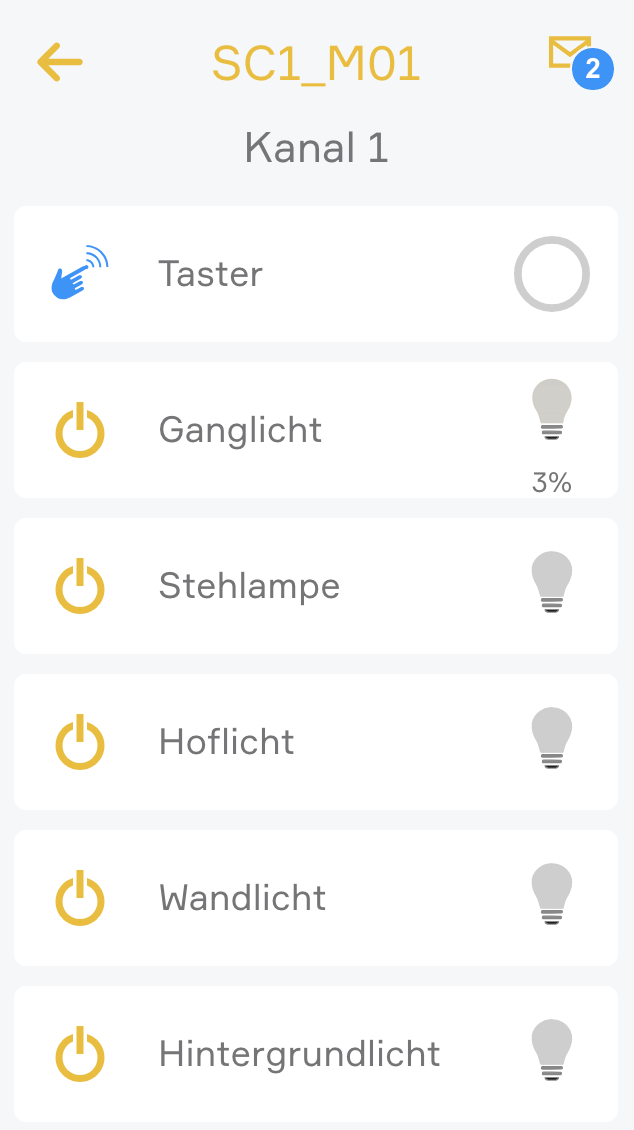
Mit der App "Dynamisches RGB Licht" lässt sich ein RGB Licht erstellen, welches aus 3 einzelnen dimmbaren Lichtern besteht. z.B. wenn 3 einzelne Dali Lichter verbunden sind, welche jeweils einen einzelnen Kanal für Rot, Grün und Blau steuern. Die App "Dynamisches RGB Licht" befindet sich unter "Alle Apps" - "Lichter"
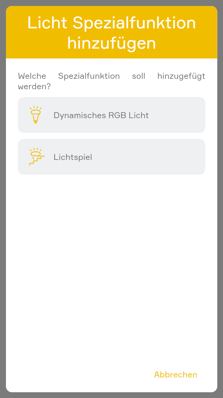
Mit "Funktion hinzufügen" > "Dynamisches RGB Licht" kann ein neues dynamisches RGB Licht erstellt werden.
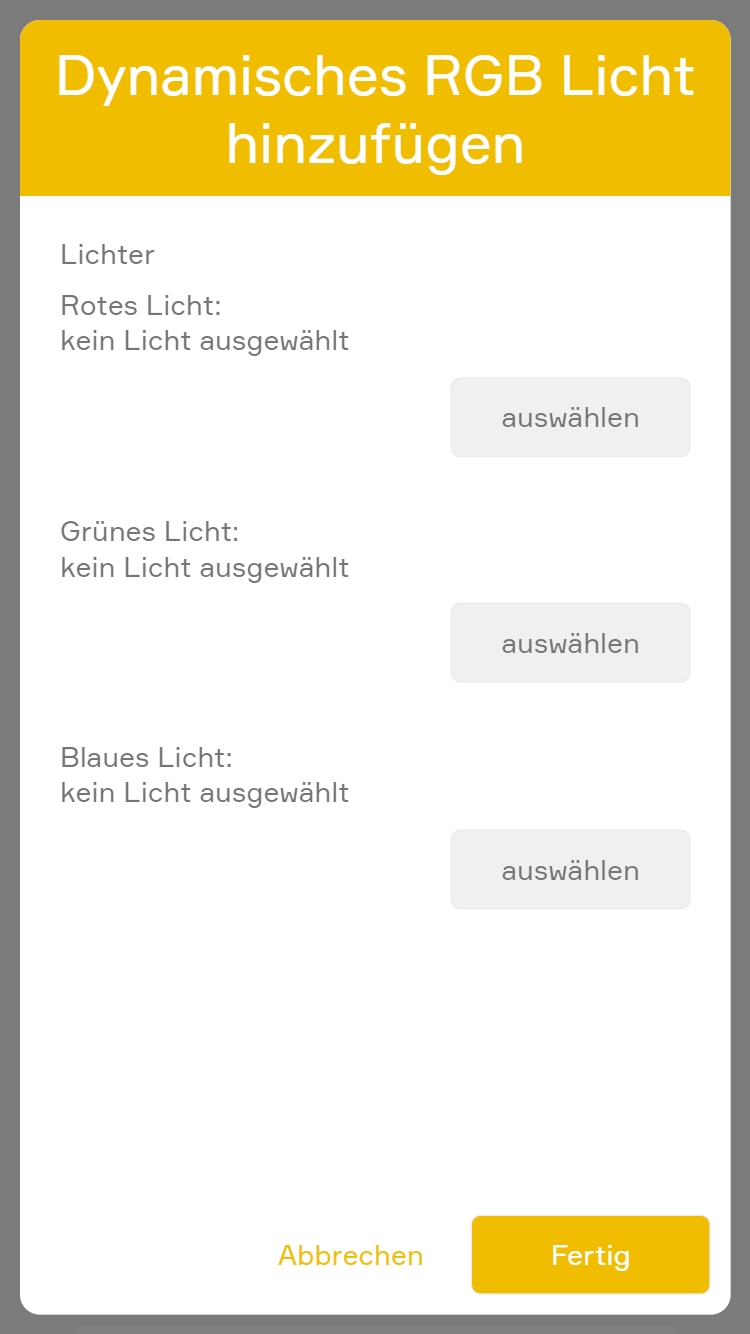
Danach öffnet sich ein Wizard, über welchen die 3 einzelnen Lichter ausgewählt werden können. Jeweils ein dimmbares Licht für Rot, Grün und Blau.
Das dynamische RGB kann gleich konfiguriert werden wie andere RGB Lichter, abgesehen von der Funktion "Farbdurchlaufzeit" und "Nur Weiß".
Siehe: RGB Konfiguration
Das dynamische RGB hat die selben Funktionen wie andere RGB Lichter, abgesehen von der Funktion "Farbdurchlauf".
Siehe: RGB Bedienung
Mit der App "Lichtspiel" lassen sich verschiedene Lichtmuster auf einer Gruppe von Lampen erzeugen. Die App "Lichtspiel" befindet sich unter "Alle Apps" - "Lichter".
Mit "Funktion hinzufügen" > "Lichtspiel" kann ein neues Lichtspiel erstellt werden.
Im Parameter Panel können dann die Lichter ausgewählt werden und in gewünschter Reihenfolge sortiert werden.
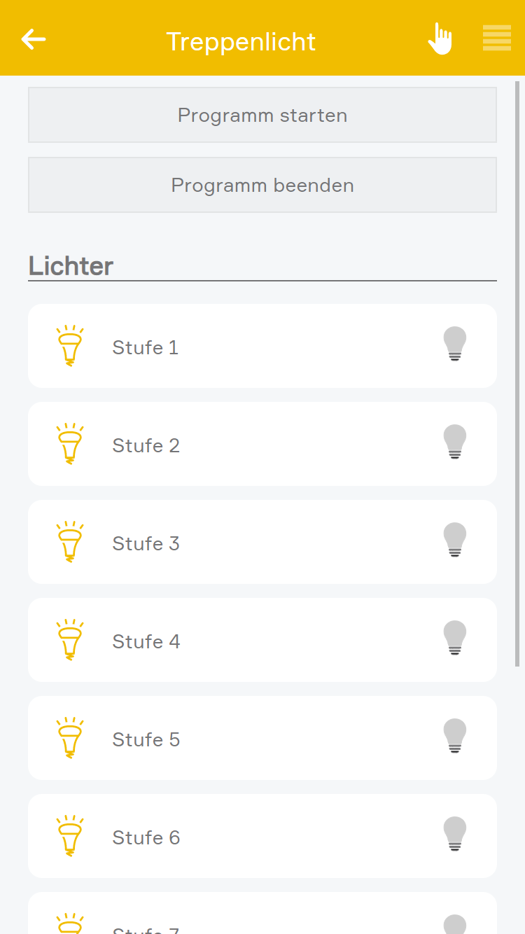
Programm starten
Mit dem Button "Programm starten" kann ein Programm gestartet werden (Details siehe unten).
Programm beenden
Mit dem Button "Programm beenden" kann ein aktuell aktives Programm wieder beendet werden.
Lichter
Hier werden die ausgewählten Lichter und der aktuelle Status angezeigt.
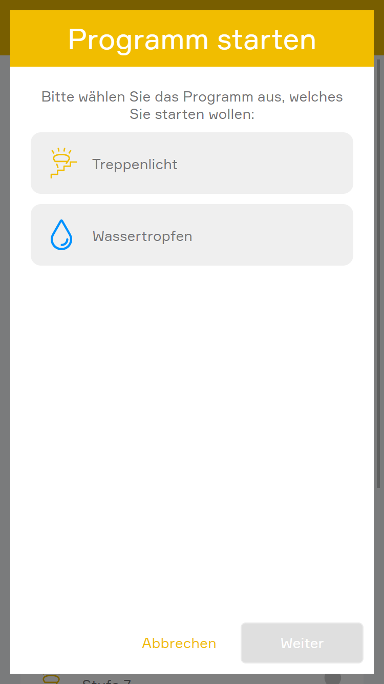
Nach einem Klick auf "Programm starten" öffnet sich ein Wizard, über welchen ein Programm gewählt werden kann. Hier kann zwischen "Treppenlicht" und "Wassertropfen" ausgewählt werden.
Beim "Treppenlicht" handelt es sich um eine Funktion, wo z.B. einzelne Stufen einer Treppe Schritt für Schritt zugeschaltet werden können.
z.B. könnte hier folgendes Muster erzeugt werden: Oberste Stufe wird eingeschaltet, 1s warten, zweite Stufe wird eingeschaltet, 1s warten, dritte Stufe wird eingeschaltet,...
Beim Beenden werden die Lichter in selber Reihenfolge ausgeschalten, wie sie eingeschalten wurden.
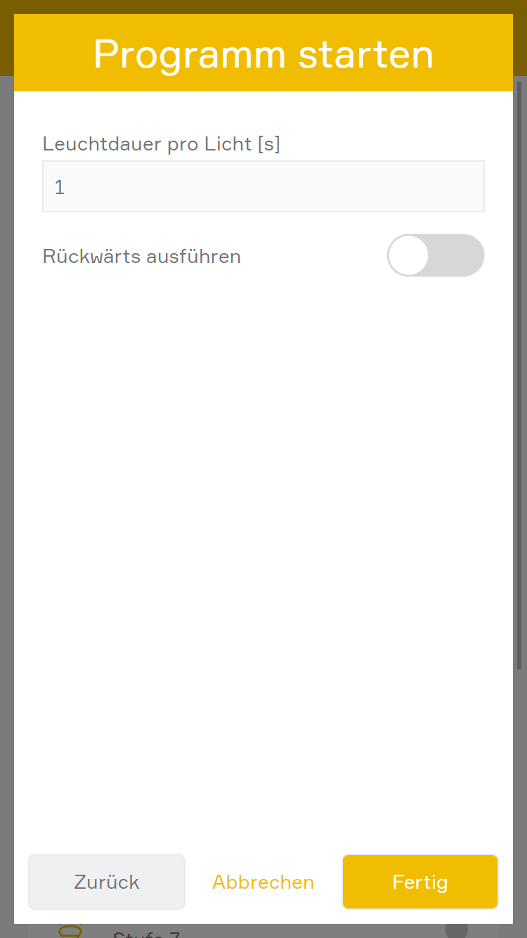
Hier können folgende Parameter vergeben werden:
Leuchtdauer pro Licht [s]: Gibt an, wie lange ein Licht leuchtet, bevor das nächste Licht dazu geschalten wird.
Rückwärts ausführen: Wenn diese Option gewählt wurde, werden die Lichter in umgekehrter Reihenfolge eingeschalten.
Bei "Regentropfen" handelt es sich um eine Funktion, wo z.B. bei LED Streifen einzelne Lichter nacheinander angesteuert werden können, um so den Effekt von fallenden Wassertropfen zu simulieren.
z.B. könnte hier folgendes Muster erzeugt werden: Oberste LED wird eingeschaltet, 1s warten, oberste LED wird ausgeschaltet, zweite LED wird eingeschaltet, 1s warten, zweite LED ausschalten, dritte LED einschalten,...
Beim Beenden werden alle Lichter ausgeschalten.
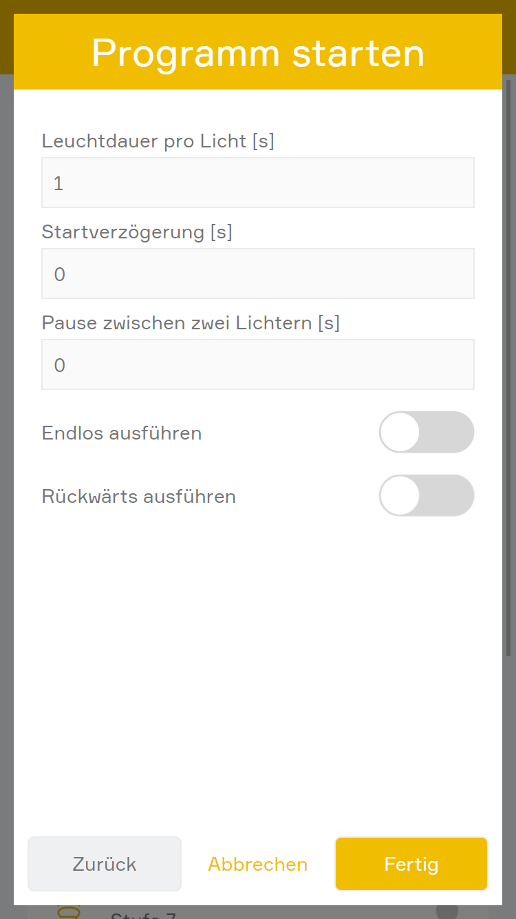
Hier können folgende Parameter vergeben werden:
Leuchtdauer pro Licht [s]: Gibt die Zeit an, wie lange ein Licht leuchten soll, bevor es wieder ausgeschalten wird.
Startverzögerung [s]: Gibt die Zeit an, wann das Programm starten soll, bzw. die Pause zwischen 2 vollständigen Durchläufen.
Pause zwischen zwei Lichtern [s]: Gibt die Zeit an, welche zwischen dem Ausschalten eines Lichts und des Einschalten des nächsten Lichts gewartet werden soll.
Endlos ausführen: Wenn diese Option gewählt wurde, wird nach dem ausführen eines Zyklus wieder von vorne gestartet.
Rückwärts ausführen: Wenn diese Option gewählt wurde, werden die Lichter in umgekehrter Reihenfolge eingeschalten.
Das Lichtspiel bietet folgende Funktionen für evon Smart Home Szenen (Dann...):
- Programm beenden: Beendet das aktuelle Programm
- Programm Regentropfen starten: Startet das Programm "Regentropfen"
- Programm Treppenlicht starten: Startet das Programm "Treppenlicht"
Lichter bieten folgende Möglichkeiten für evon Smart Home Logiken:
-- Dauerhaft EIN: Ob das Licht dauerhaft eingeschalten ist (lesen und schreiben)
-- Fehler: Ob ein Fehler erkannt wurde (lesen)
-- Licht eingeschaltet: Ob das Licht eingeschalten ist (lesen)
-- Sperren: Ob das Licht gesperrt ist (lesen)
-- Externer Bewegungsmelder sperren: Hiermit kann die Aktivierung des Lichts durch einen verknüpfen Bewegungsmelder aufgehoben werden (schreiben)
-- Skalierte Helligkeit: Die skalierte Helligkeit in Prozent von dimmbaren Lichtern lesen (lesen)
-- Helligkeit setzen: Die skalierte Helligkeit in Prozent bei dimmbaren Lichtern setzen (schreiben)
-- Modus Nur Weiß aktiv: Gibt an, ob der Modus Nur Weiß aktiv ist (lesen, nur bei RGBW Lichtern)
-- Automatik Programm aktiv: Gibt an, ob der automatische Farbdurchlaufsmodus aktiv ist (lesen, nur bei RGBW Lichtern)
-- Farbtemperatur setzen: Die Farbtemperatur eines DALI-Lichts setzen (schreiben)
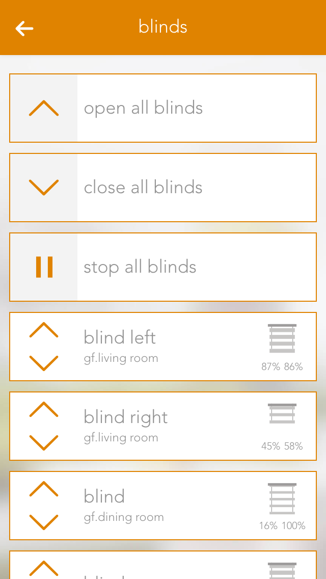
The app “Blinds” lets you operate and configure all shading elements in your system. You also have pre-defined functions such as “open all blinds” and “close all blinds”.
You can find Blinds under “all apps”.
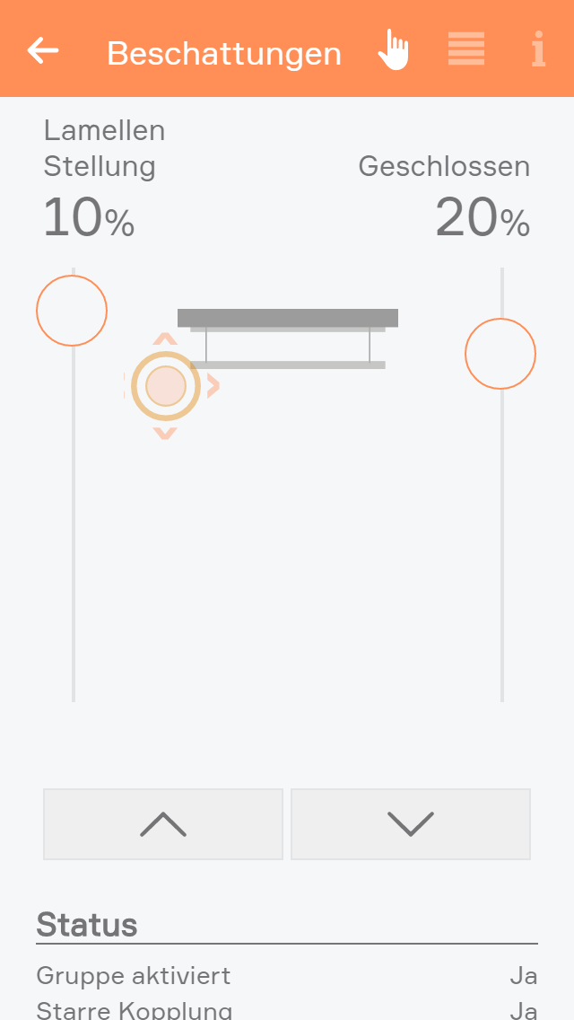
You can open or close your shading element using the arrows in the left-hand side of the object panel. The right-hand side of the panel shows the current position and the angle of the blinds.
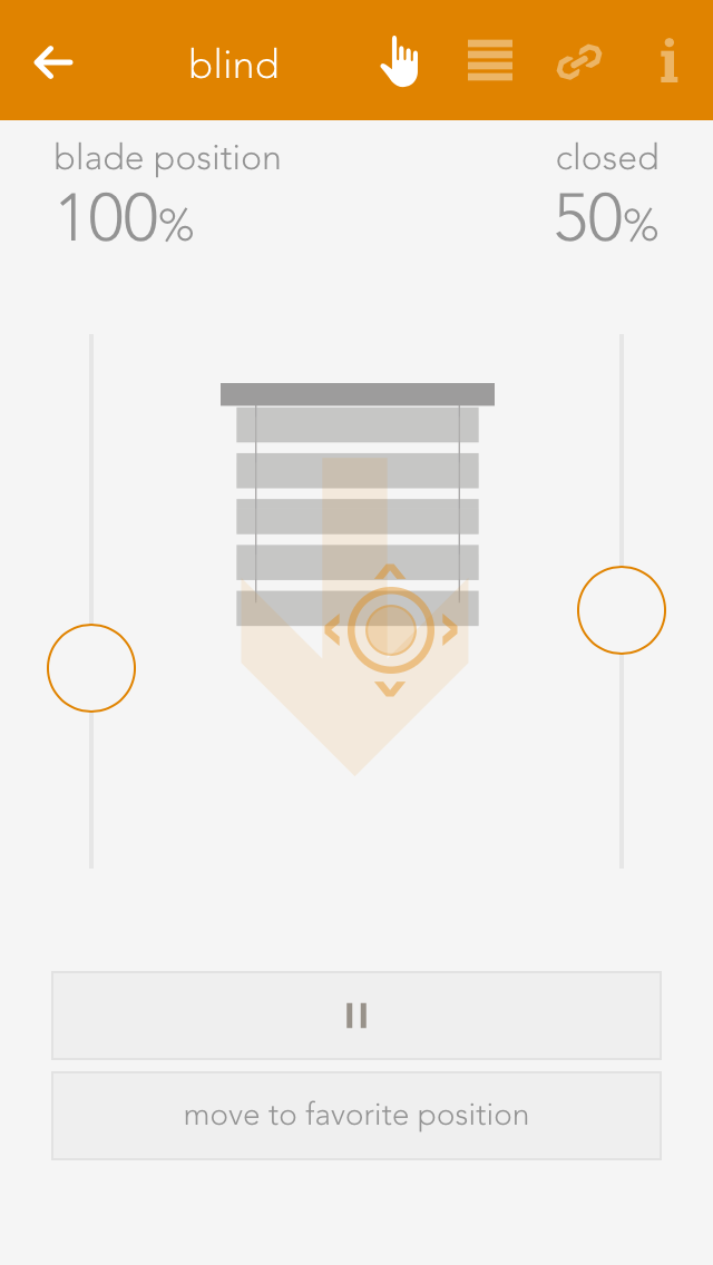
You can also operate each blind element via the operator panel by using the sliders on the right and on the left, or dragging the point in the middle of this window to the desired position. If you have defined a favourite position and wish to use it, simply click on the button “go to favourite position”.
Die Beschattung bietet folgende Funktionen für evon Smart Home Szenen (Dann...):
Beschattungselemente können unter den erweiterten Einstellungen von Universalszenen ausgenommen werden. Für ausgenommene Elemente werden die Szenen-Funktionen "Alle..." nicht angewendet.
Apart from giving the shading elements individual names, you can customize them further to suit your needs.
Mode
This option is available when an 'evon Smart Home Blind 1344' (Schlotterer RETROLux) module is used. It allows to change the operation mode from 'standard blind' to 'without working position' or 'with working position'. In this case, 'working position' refers to a blind with a mechanical working position.
With working position
This mode is meant for use with the Schlotterer RETROLux venetian blind, which has a mechanical working position. It allows you to change the slat position with a short button press and to switch between 'closed' and 'working position'. In this mode, the slats can only be adjusted to a certain limit, which is caused by the underlying mechanical construction of these blinds.
Without working position
Choose this mode if you own a Schlotterer RETROLux venetian blind, which does not not have a working position. This mode grants you the ability to simulate a working position.
Type
Type lets you select whether the blind is a jalousie, a rolling shutter or a window (windows will be dealt with in an extra chapter). The jalousie has a position, an angle of the slats and a turnaround time, all of which must be considered in the calculation. A rolling shutter does not have an angle.
Vertical jalousie
If you have a jalousie that opens and closes vertically, then you can configure it here. If this is activated, you are then presented with a further option defining the direction you wish the jalousie to open.
Remove from universal scene
A universal scene could be “open all blinds”. However, if you want this shading element to be excepted from this universal scene, then activate this option.
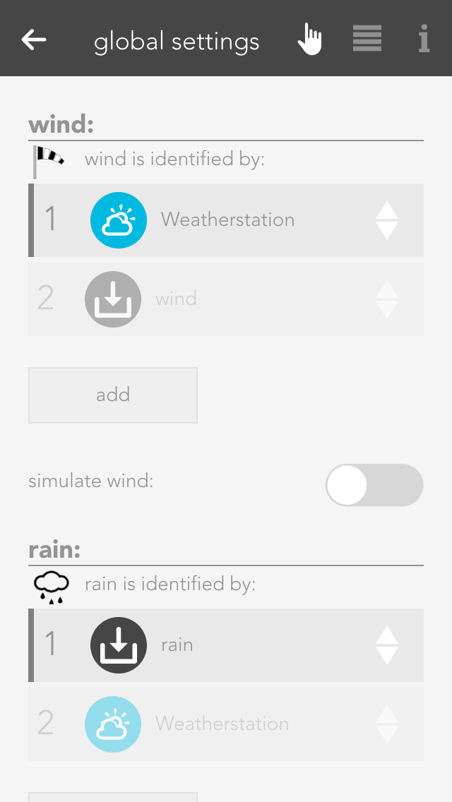
Remove from wind-lock
If you do not want this blind to open in strong wind, then activate this option. If this option is not visible, then activate the wind-lock in the settings “all-apps – settings – shading”.
Lock blind
Use this option to lock a blind, which means that the shading position can no longer be changed via the app or the button.
Close at dusk
If you want the shade to close at dusk, then activate this option.
Reserve
If you have a module that has reserve connections, i.e. blinds are not connected to every output, then these elements are still displayed. The reserve function allows you to hide unused shading elements in the app. If you wish to see these unused elements, activate them in the corresponding module in the hardware section.
Extended parameter
If you use the 'evon Smart Home Blind 1344' module in combination with a Schlotterer venetian blind (and select the correct operation mode) additional options will be available to you here.
Those refer to the varied motion times, which are specific to Schlotterer blinds, like working position/snapping times. This settings are pre configured for optimal operation. In case you encounter any problems when switching between positions (working mode/closed) please contact your evon Smart Home partner, who can adjust those settings for you.
Travel time wizard
This wizard lets you easily and simply determine the travel times for your shading element. Simply follow the instructions and your travel times will be configured for you.
Use these travel times for all blinds
Pressing this button opens a dialog where you can have all blinds use these travel times. This is useful if all blinds are of the same type and you do not wish to have individual times for each blind.
You can save your favourite blind position either by entering the values by hand or pressing the button “use current position as favourite”. The favourite position can be triggered via a scene.
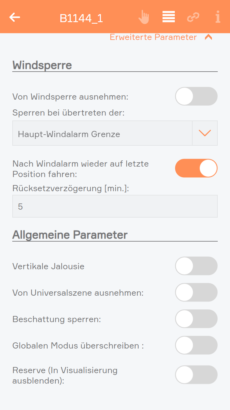
Windsperre:
Von Windsperre ausnehmen
Wenn Sie nicht wollen, dass sich ein Beschattungselement bei zu starkem Wind öffnet, so müssen Sie diese Option aktivieren. Wenn diese Option nicht sichtbar ist, so müssen Sie erst in den Einstellungen (Alle Apps – Einstellungen – Beschattung) die Windsperre aktivieren.
Sperren bei übertreten der Grenze
Wenn das Beschattungselement bei zu starkem Wind gesperrt werden soll kann hier bestimmt werden, ob diese bei der Haupt-Windgrenze, Windgrenze 1 oder Windgrenze 2 gesperrt werden soll. Die Grenzen können unter Einstellungen > Globale Einstellungen definiert werden.
Nach Windalarm wieder auf letzte Position fahren:
Wenn Sie wollen, dass ein Beschattungselement nach dem Windalarm wieder auf die letzte Position fährt, so müssen Sie diese Option aktivieren. Wenn diese aktiviert wurde, erscheint ein Eingabefeld, in dem Sie eine Verzögerungszeit von 5 bis 60 Minuten wählen können, welche ablaufen muss, bevor die Beschattung nach dem Windalarm auf die letzte Position zurück fährt.
Allgemeine Parameter:
Vertikale Jalousie
Wenn Sie eine Jalousie haben, die vertikal schließt bzw. öffnet, so können Sie dies hier einstellen. Haben Sie dies aktiviert, erscheint eine weitere Option mit der Sie die Öffnungsrichtung bestimmen können.
Von Universalszene ausnehmen
Als Universalszene gilt z.B. „Alle öffnen“. Wollen Sie aber, dass ein Beschattungselement nicht über diese Universalszenen mitgeschalten wird, so müssen Sie diese Option aktivieren.
Beschattung sperren
Mit dieser Option können Sie ein Beschattungselement sperren. D.h. die Position des Beschattungselementes kann nicht mehr über die App oder Taster verändert werden.
Globalen Modus überschreiben
Mit der Option können Sie für diesen Kanal den globalen Modus für die Steuerung mittels Taster überschreiben (Kurzer Tastendruck - ganz auf, Kurzer Tastendruck - Lamellen stellen)
Bei Dämmerung schließen
Wollen Sie, dass sich dieses Beschattungselement bei Dämmerung schließt, so müssen Sie diese Option aktivieren.
Reserve
Wenn Sie ein Modul haben, an dem Sie nicht alle Beschattungselemente angeschlossen haben, werden trotzdem auch die Elemente angezeigt, an denen nichts angeschlossen ist. Mit Reserve können Sie nicht verwendete Beschattungselemente in der App ausblenden. Über die Hardware und das entsprechende Modul können Sie dieses Beschattungselement wieder einblenden.
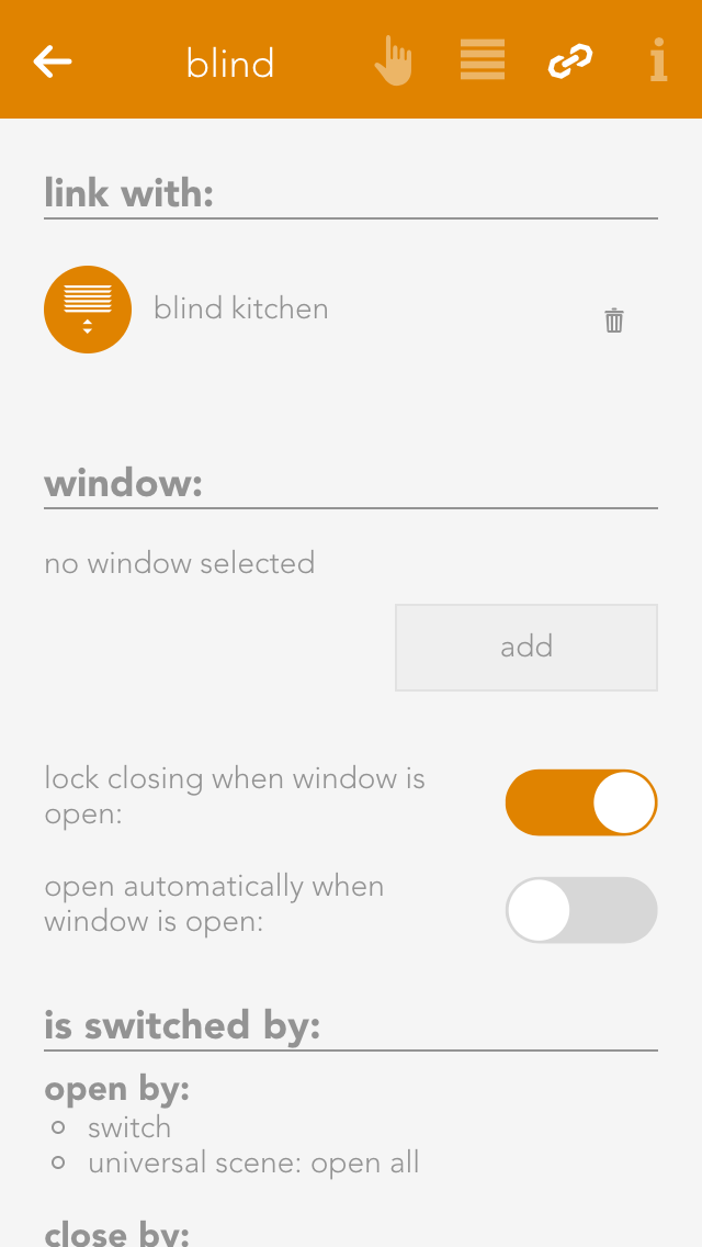
Linking allows you to connect your shading elements to other elements in your evon Smart Home.
Connect with
If you want two shading elements to always have the same position and slat angle, then use this “connect with”. Navigate to “connect with” and press “select” to choose the shading element you wish to connect to.
Über die Gruppenfunktion lassen sich mehrere Beschattungen zu einer Gruppe zusammenfassen. Dadurch werden alle gleichzeitig geschalten.
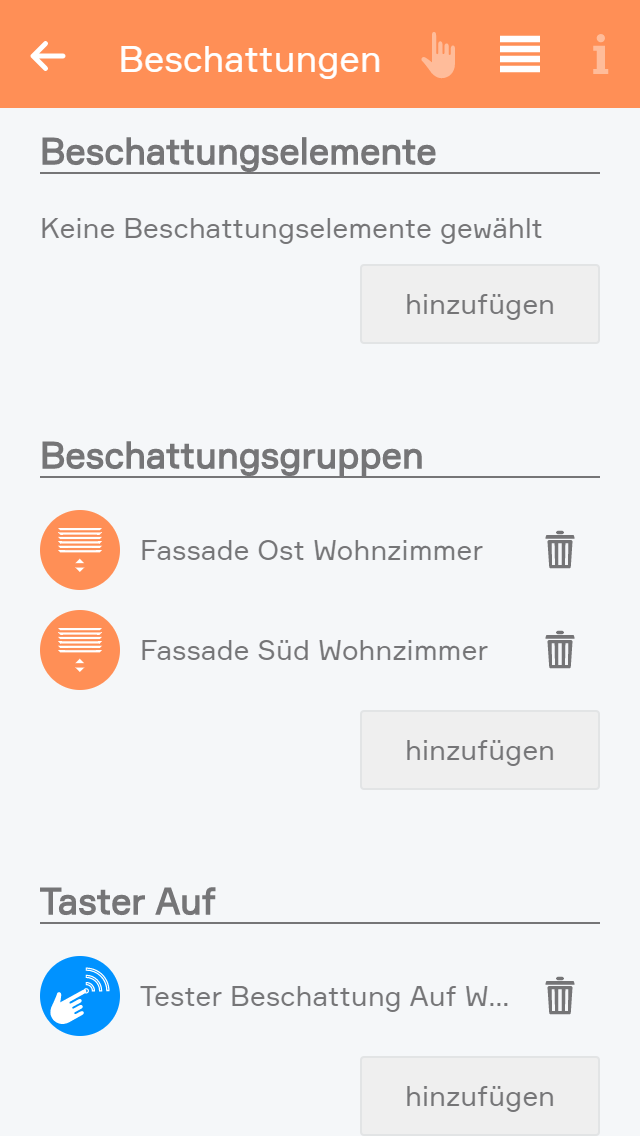
Um eine neue Beschattungsgruppe anzulegen, wählen Sie "Neue Beschattungsgruppe" innerhalb der Beschattungs-App.
Eine neue Beschattungsgruppe wird erstellt.
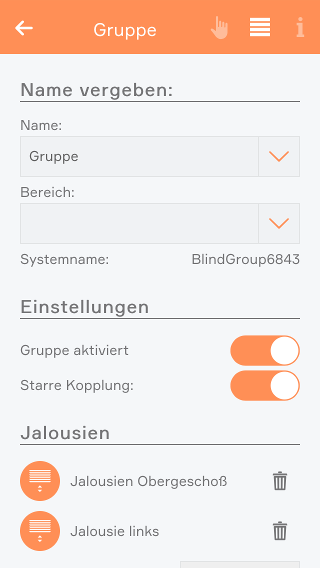
In den Einstellungen der Gruppe sollten Sie als erstes einen Namen vergeben und einen Raum zuordnen.
Hier haben Sie außerdem die Möglichkeit, die Gruppe zu deaktivieren. Dadurch können Sie eine bereits konfigurierte Gruppe temporär abschalten, ohne sie löschen zu müssen.
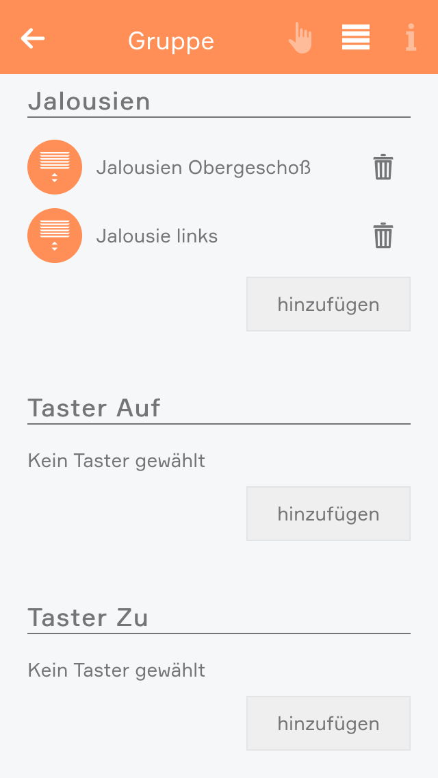
Fügen Sie nun mehrere Beschattungselemente hinzu. Sie habe die Möglichkeit die Gruppe in 2 Betriebsarten zu betreiben: „Starre Kopplung“ oder „Lose Kopplung“.
Starre Kopplung: Starre Kopplung: Dieser Modus ist sinnvoll, wenn Sie Beschattungselemente der gleichen Größe (Fensterhöhe) zu jedem Zeitpunkt auf derselben Position wünschen. Alle Beschattungselemente einer Gruppe fahren somit immer auf dieselbe Position und den Lamellenwinkel (falls vorhanden). Dabei ist es unerheblich ob der Befehl als Einzelbefehl über die App, als Gruppenbefehl über die App, den Autark-Taster oder den Gruppentaster erfolgt ist, die Position wird immer synchronisiert.
Lose Kopplung: Dieser Modus erlaubt das gemeinsame Heben und Senken von unterschiedlichen Beschattungselementen über einen oder mehrere Gruppentaster. Die Beschattungselemente können aber jederzeit über Einzelbefehle aus der App oder den Einzeltaster (Autarkfunktion) individuell positioniert werden.
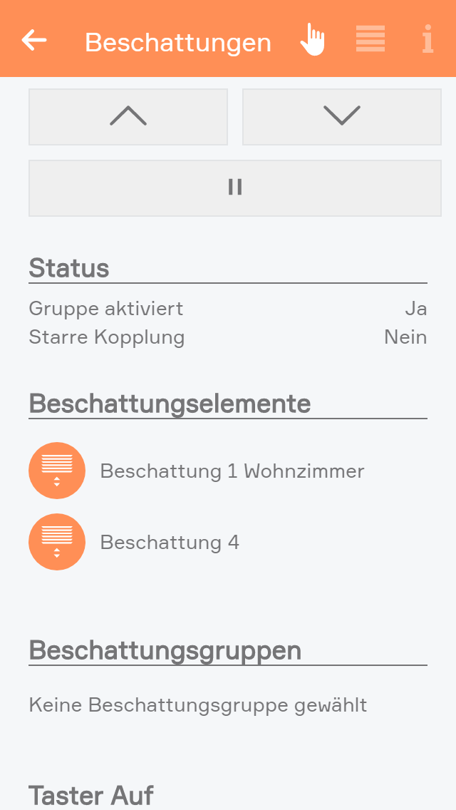
Bei einer Beschattungsgruppe mit starrer Kopplung können Sie im Operator Panel mit den gewohnten Bedienelementen die Beschattungen in beliebige Positionen bewegen, öffnen, schließen und stoppen.
Bei einer Beschattungsgruppe mit loser Kopplung können Sie im Operator Panel die Beschattung öffnen, schließen und stoppen.
Bei Beschattungsgruppen mit loser Kopplung haben Sie zusätzlich die Möglichkeit andere Beschattungsgruppen hinzuzufügen. Dadurch ist es möglich mehrere Beschattungsgruppen mit externen Tastern zeitgleich zu steuern, diese Gruppen jedoch auch noch getrennt über andere Taster zu steuern.
Settings contains the configuration for general settings that are valid for all shading element. Navigate to “all apps – settings – blinds”.
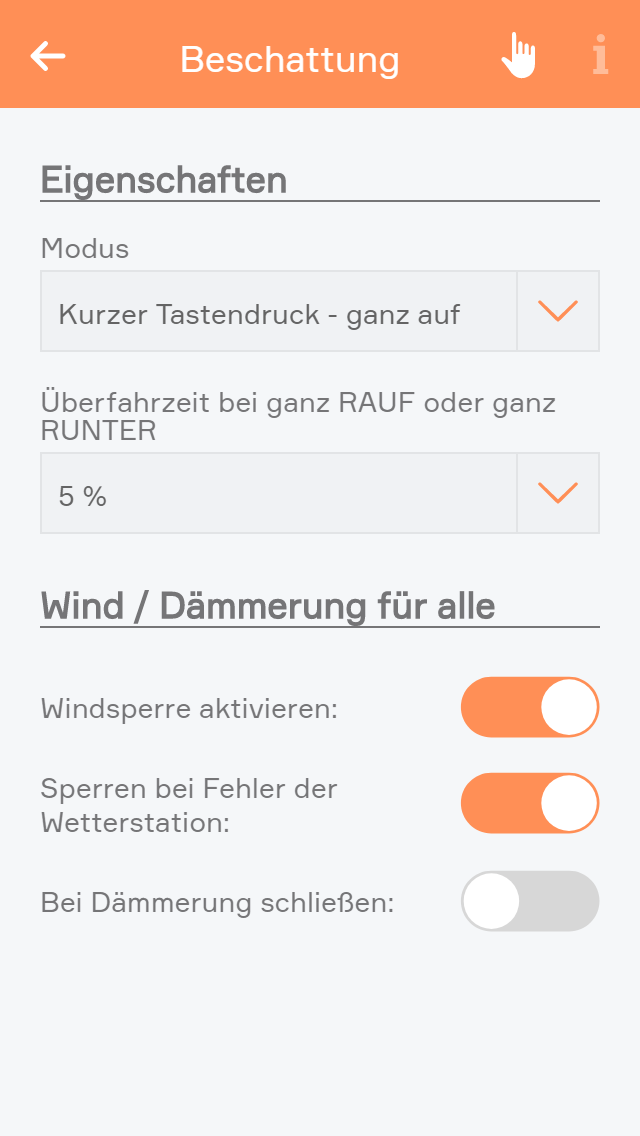
Mode
Short button press – completely up: If the blinds button is pressed for a short period of time, then the blinds will travel in the desired direction until either the blinds are fully open/closed, or a further press of the button causes them to stop where they are. A long button press sets the angle for the slats, i.e. after a wait time to correctly identify a long button press, the blind slats begin to turn until the button is released.
Short button press - set slats: A short button press changes the angle of the blinds and a long button press completely opens or closes the jalousie. A second button press interrupts the travel and the jalousie stops where it is.
Over-travel time
The over-travel time lets you define the percent of time to increase the time that the jalousie takes for completely UP to completely DOWN. This makes sure that the blinds are really open or closed.
Activate wind lock
If you have activated this option, then all shading elements are closed if it is windy. If you want to exempt elements from this wind lock, it can be done for each individual element.
Close at twilight
If “close at twilight” is selected, then all blinds will close as soon as twilight is detected. If you do not want all blinds to close at twilight, then deactivate “close at twilight” for each individual blind. In addition, you can also delay the closing at twilight by entering the number of minutes you wish to wait after twilight until the blinds close.
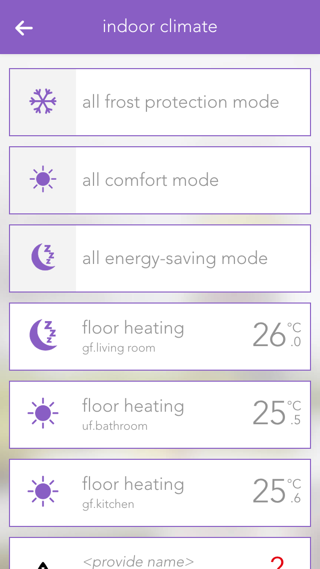
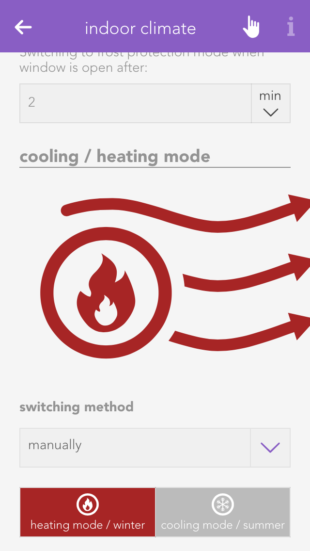
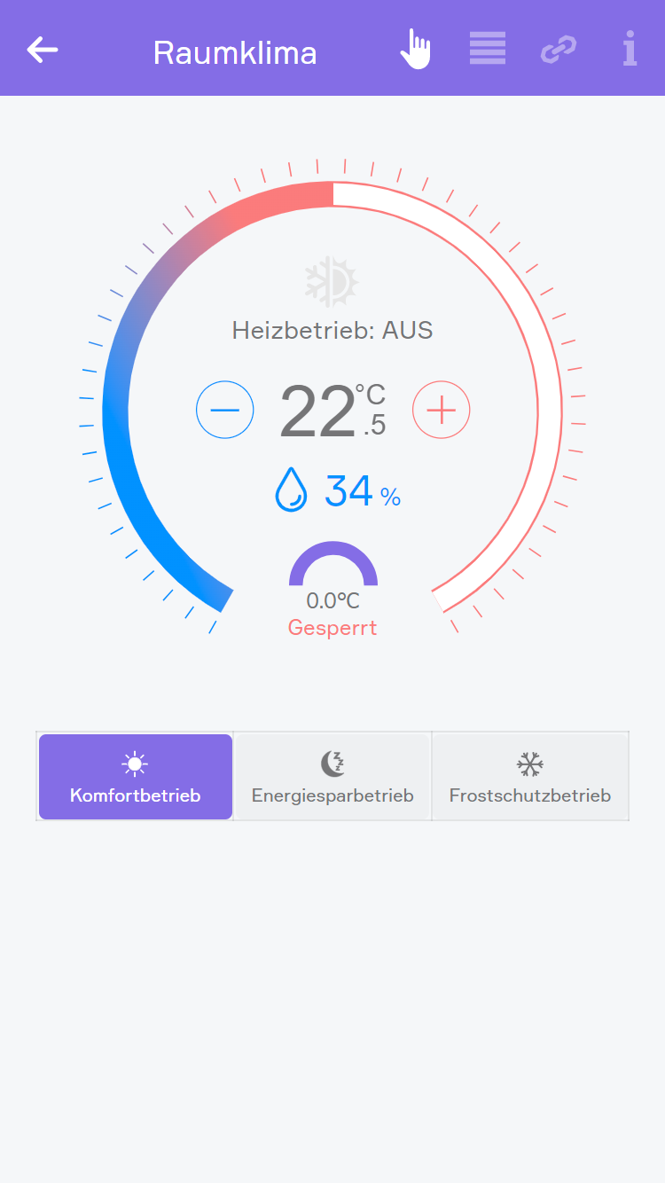
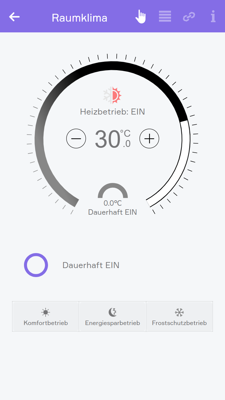
The app “indoor climate” lets you operate and configure all room climate elements in your system. You also have the pre-defined central functions “all frost protection mode”, “all comfort mode” and “all energy saving mode”.
The app is located under “all apps” – “indoor climate”.
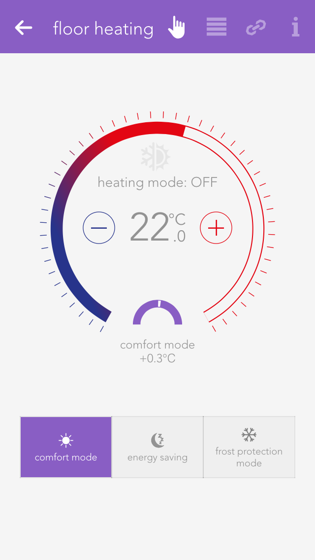
Clicking on the left-hand area of the object panel switches back and forth between comfort mode and energy saving mode.
You can also select the operating mode using the three buttons located next to each other in the operator panel. The desired temperature can be adjusted in the circle above these buttons via the “+” and “-“ buttons, or you can simply click on the position in the circle that you want.
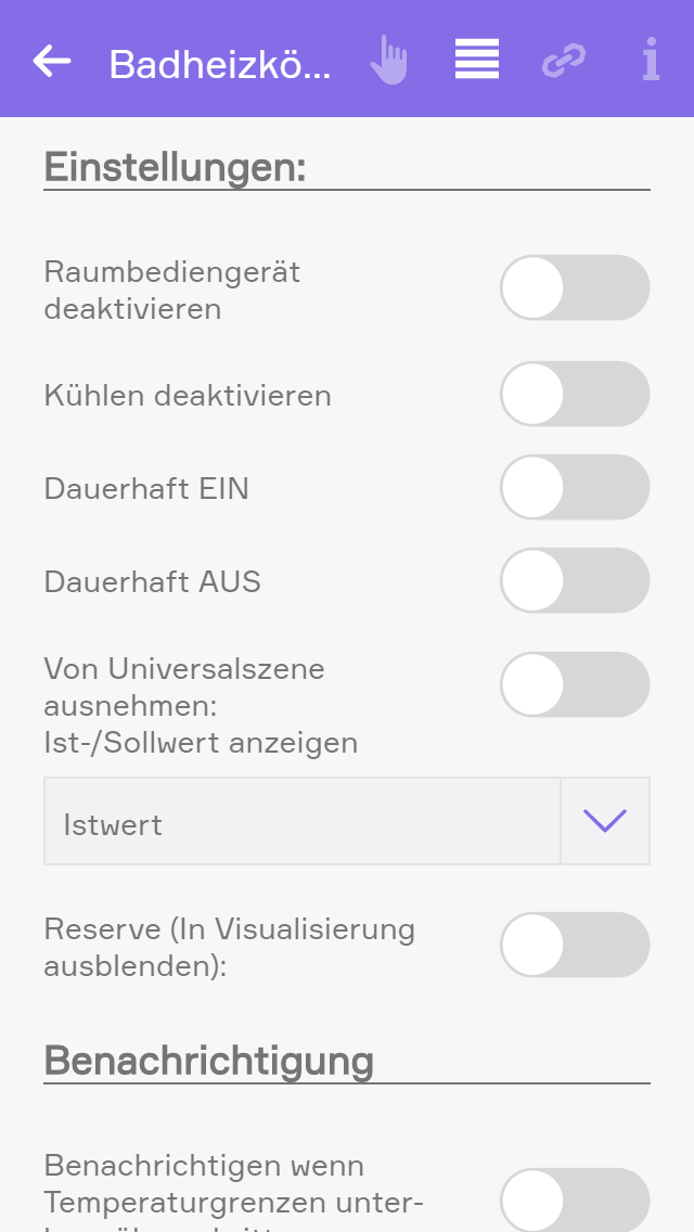
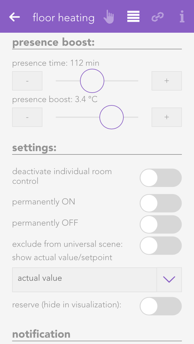
Deactivate individual room control
If you have a module type C1144, you can deactivate a connected room control panel with this setting. In this case, only the actual value is taken from the room control panel. All other values are ignored.
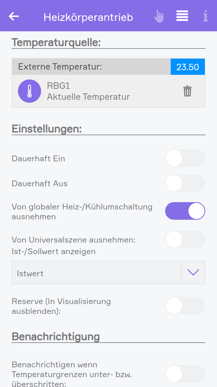
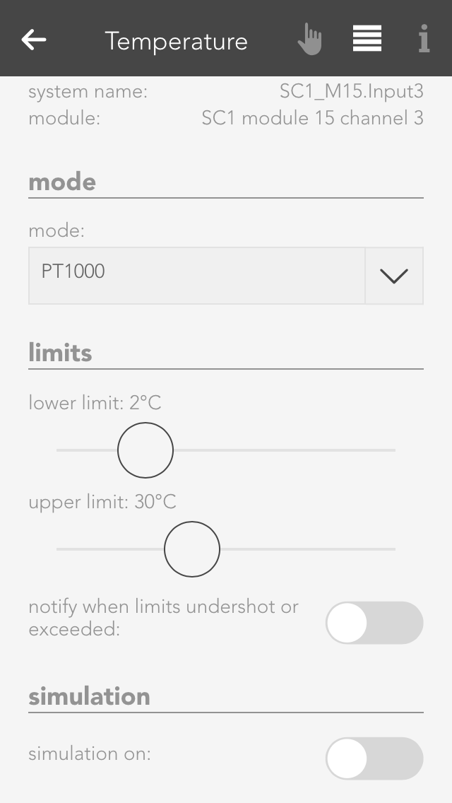
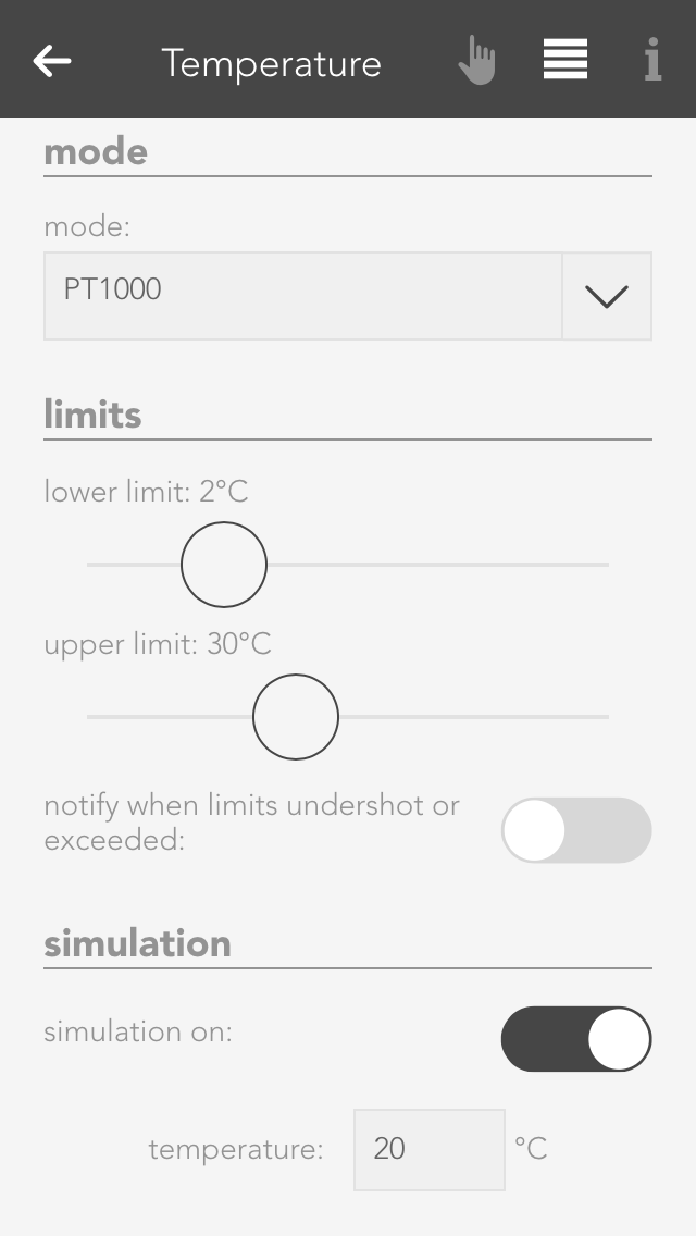
External actual value
If you have a module type C1244, you can activate this setting to receive the actual value from another source than a connected PT1000. If you use this setting, you will have to choose the new source in the linkpanel.
Cooling disabled
This setting allows you to deactivate cooling for the connected climate device. Additionally, while this option is active, the cooling mode from the global settings will also be ignored.
Permanent ON/OFF
The valve output can be permanently switched on or off, independently of the current temperature and the current operating mode.
Remove from universal scene
The valve output can be permanently switched on or off, independently of the current temperature and the current operating mode.
Display actual/desired value
This value determines whether the actual or desired value should be displayed in the object panel.
Reserve
Even if not all room climate channels are connected to a module, all four control elements are still displayed for this module. If you want to hide these unconnected control elements, then mark them as reserved. You can unhide them via the app “hardware” (all apps – “hardware”).
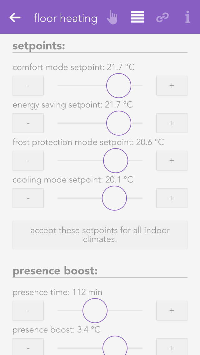
The desired values for the various operating modes are defined here. Clicking on the button “use this desired value for the entire room climate” opens up a dialogue with which the desired values in this room climate element can also be used for all other elements.
Bei einem Heizkörperantrieb kann zudem eine externe Temperaturquelle gewählt werden. Wenn keine externe Temperaturquelle ausgewählt ist, wird die aktuelle Temperatur vom Heizkörperantrieb geliefert.
If the presence button on the room control panel is pressed, the desired temperature of the room is increased by the defined value and time period.
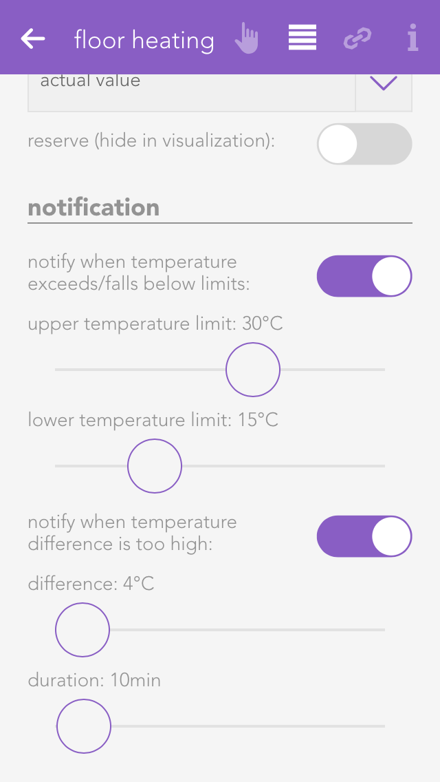
The item “temperature limit” lets you define a temperature limit, i.e. you can react with a scene if the value falls below or exceeds the limit. You can also activate notifications for falling below or exceeding the limit via “notifications for temperature limits”.
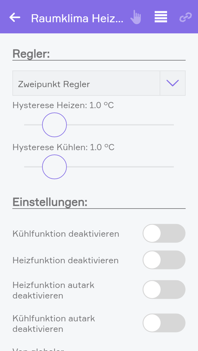
Bei C1144 und C1244 Modulen mit Firmware 4.0 oder höher kann die Art des Reglers eingestellt werden. Dieser kann entweder als Zweipunkt oder PWM Regler konfiguriert werden.
Zweipunkt Regler
Der Zweipunkt Regler ist die einfachste Form eine Heiz- oder Kühl-Regelung zu realisieren. Der Zweipunktregler vergleicht den Istwert mit dem Sollwert und schaltet in Abhängigkeit der Hysterese den Ausgang bei Überschreitung oder Unterschreitung Aus oder Ein. Die Hysterese dient dazu die Schalthäufigkeit (Frequenz) des Ausgangs zu begrenzen.
Folgende Einstellungen können gesetzt werden:
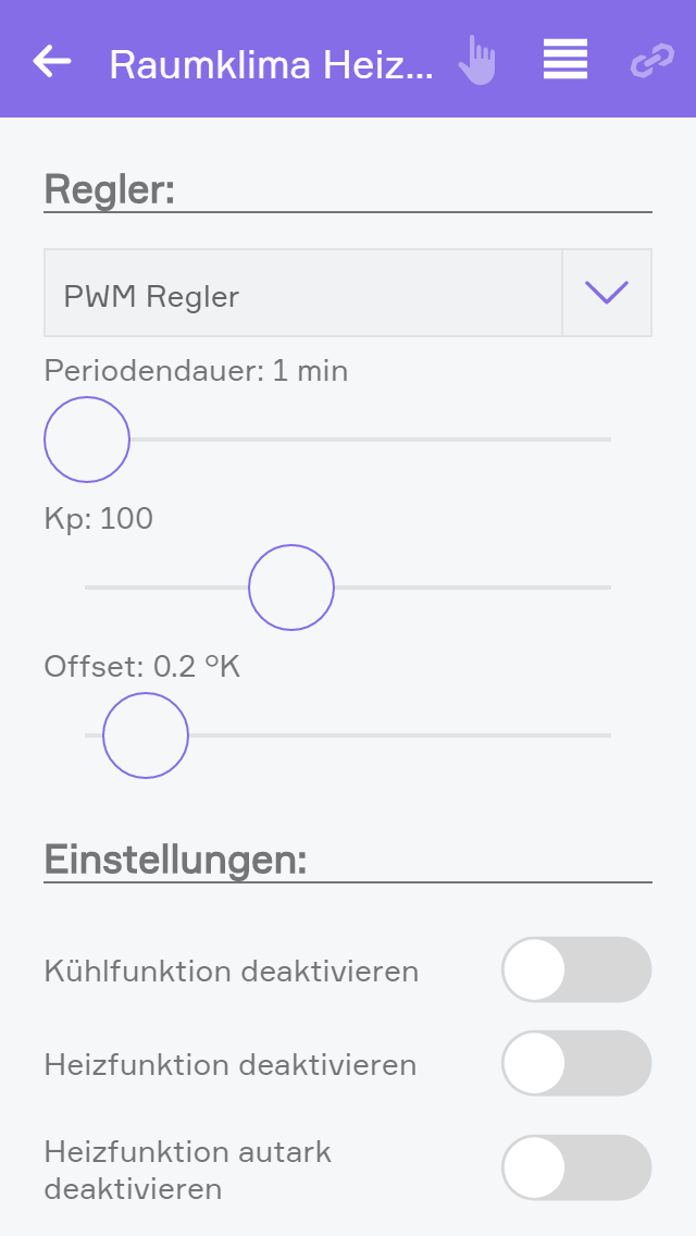
PWM Regler
Der PWM Regler (Pulsweitenmodulations-Regler) ist eine erweiterte Möglichkeit zur Regelung von Heiz- oder Kühlsystemen. Der PWM Regler nützt die Trägheit von Systemen aus, um im Vergleich zum Zweipunktregler (Ein, Aus) sehr viele Ausgangszustände abbilden zu können. Der PWM Regler arbeitet dabei auch nur mit einem digitalen Ausgangssignal, dieses wird jedoch innerhalb einer definierten Periodendauer so geschaltet, dass in Abhängigkeit der Soll-/Ist-Temperaturabweichung der Ausgang mit unterschiedlichen Puls- (Ein) und Pausenzeiten (Aus) angesteuert wird. Ein träges System (z.B.: Thermostellantrieb in einer Fußbodenheizung) kann durch diese Art sehr intelligent von 0-100% geregelt werden.
Beispielhafte Funktionserklärung:
Solltemperatur 22°C, Isttemperatur 21,3° ergibt eine Abweichung von 0,7°C. 0,7 + Offset von 0,2 multipliziert mit einem Kp von 100 ergibt einen Wert von 90%. Der PWM Regler wird in diesem Fall bei einer Periodendauer von 300sec (5min) den Ausgang (Ventil) 270sec aktiv ansteuern (90% von 300sec).
Periodendauer
Die Periodendauer definiert den gesamten Zeitbereich für die Berechnung der Puls- Pausenzeit. Die Periodendauer muss der Zeitdauer für das vollständige Ansprechen des verknüpften Ausgangs entsprechen.
Beispiel Thermostellantrieb: Die Periodendauer entspricht der Zeit welche vergeht, bis der Stellantrieb nach der Ansteuerung vollständig geöffnet ist.
Beispiel Infrarotheizung: Die Periodendauer entspricht der Zeit welche vergeht, bis das Panel nach der Ansteuerung die maximale Heizleistung /Wärme abstrahlt.
Kp
Der Verstärkungsfaktor Kp definiert die Verstärkung des berechneten Ausgangswertes (Pulse/Pause) in Abhängigkeit von Soll-/Isttemperatur. Eine Erhöhung von Kp führt bei gleichbleibender Abweichung von Soll-/Isttemperatur zu einem erhöhten Ausgangswert. Kp kann somit als ein Multiplikationsfaktor der Abweichung betrachtet werden.
Offset
Eine reine Multiplikation über den Verstärkungsfaktor Kp würde nicht zum genauen erreichen von Solltemperatur gleich Isttemperatur führen. Der Offset führt somit eine leichte Manipulation der berechneten Temperaturabweichung aus und führt somit zur schnelleren Erreichung der gewünschten Isttemperatur. Der Wert für das Offset sollte im Regelfall immer unter 1°C ausreichend sein.
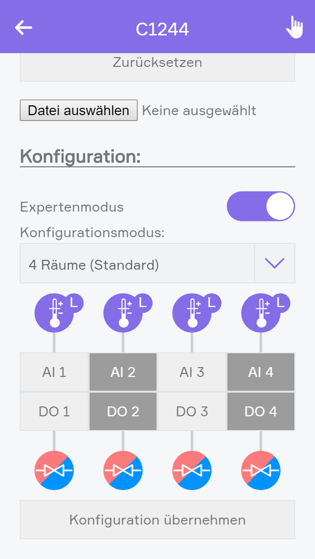
Bei den Klimamodulen C1144 und C1244 mit Firmware Version 4.0 oder höher steht ein Expertenmodus zur Verfügung über welchen die allgemeine Konfiguration des Moduls erfolgt. Dieser muss direkt im Modul unter Hardware konfiguriert werden.
Expertenmodus
Wenn der Expertenmodus aktiviert ist kann der Modus des Moduls und die Ein und Ausgänge entsprechend der tatsächlichen Ein- und Ausgänge konfiguriert werden.
Außerdem werden dann auch in der Detailansicht des Moduls die Ein- und Ausgänge angezeigt.
Konfigurationsmodus
Der Konfigurationsmodus kann auf folgende Werte eingestellt werden, welche weiter unten erklärt werden:
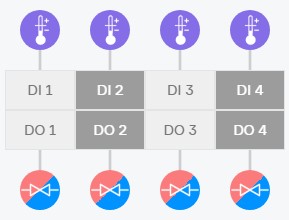
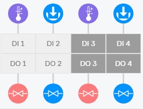
Durch Auswahl von DI/AI 1-4 können die Eingänge konfiguriert werden.
Istwertquelle
Definiert von wo der Istwert für den Regler kommt. Je nach Modus stehen folgende Werte zur Verfügung:
Eingangsmodus
Definiert was am Eingang angeschlossen ist. Je nach Modus stehen folgende Werte zur Verfügung:
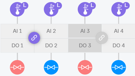
Durch das zusätzliche "L" bei Raumbediengeräten wird eine Light-Variante symbolisiert. Dabei handelt es sich um einfache Temperaturfühler.
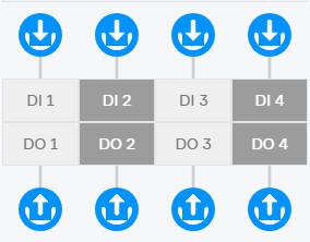
Durch Auswahl von DO 1-4 können die Ausgänge konfiguriert werden.
Ausgangsmodus
Definiert was am Ausgang angeschlossen ist. Je nach Modus stehen folgende Werte zur Verfügung:
Sperrkontakt
Definiert durch welchen Sperrkontakt das Ventil gesperrt werden soll. Dafür muss ein entsprechender Eingang als Sperrkontakt konfiguriert sein.
Sperrkontakte können nur beim Modul C1144 verwendet werden.
Modus: 4 Räume (Standard)
Dieser Modus eignet sich für Räume in welchem nur ein Ventil zum Heizen und/oder Kühlen verwendet wird. Wie zum Beispiel bei der Standard Fußbodenheizung.
Somit können 4 Räume auf einem Modul konfiguriert werden.
In diesem Modus kann kein Sperrkontakt vergeben werden.
Modus: 2 Räume
Dieser Modus eignet sich für Räume, in welchen zwei getrennte Ventile verwendet werden. Zum Beispiel ein Ventil zum Heizen und ein Ventil zum Kühlen.
Somit können 2 Räume konfiguriert werden.
Hier kann Eingang 2 und Eingang 4 als Sperrkontakt oder Digitaler Eingang verwendet werden.
Modus: Universal
Dieser Modus eignet sich für Räume in welchen ein Mehrstufiges Heiz- oder Kühlsystem vorhanden ist. Zum Beispiel wenn über den Fußboden geheizt und gekühlt wird und zusätzlich über die Decke gekühlt wird oder bei einer gestaffelten Infrarot Heizung über Fußboden, Decke und Wand.
Hier kann für die Eingänge 2-4 die davor liegenden Eingänge als Istwert verwendet werden, wenn zum Beispiel das Raumbediengerät am Eingang 1 angeschlossen wurde. Die anderen Eingänge können dann als Sperrkontakte oder Digitale Eingänge verwendet werden.
In diesem Modus wird pro Regelkreis ein eigener Regler angelegt, um eine erleichterte Bedienung zu erhalten, können diese in einer Zonenregelung zusammengefasst werden.
Zusätzlich ist es durch Klick auf den Verknüpfungs-Button möglich, zwei Kanäle zu einer gemeinsamen Regelung zusammenzufügen um beispielsweise eigene Heiz- und Kühlventile mit einer Regelung verwenden zu können.
Modus: Ohne Autark Funktion
In diesem Modus werden die Regler am Modul deaktiviert. Dann werden die Ein- und Ausgänge wie Digitale Ein- und Ausgänge verwendet und müssen zum Beispiel über die Logik ausgewertet und geschalten werden.
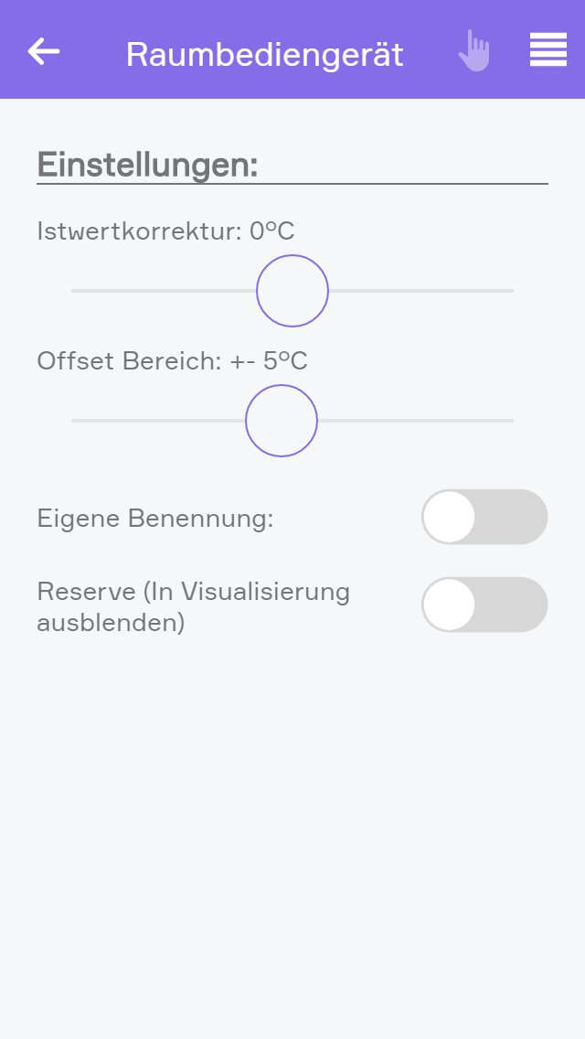
Wenn sich das Modul im Expertenmodus befindet kann in der Anzeige der Kanäle, in den Parametern des Raumbediengerätes oder des Temperaturfühlers eine Korrektur des Istwertes eingestellt werden. Dadurch wird der vom Sensor gemessene Istwert um den eingestellten Wert erhöht/vermindert.
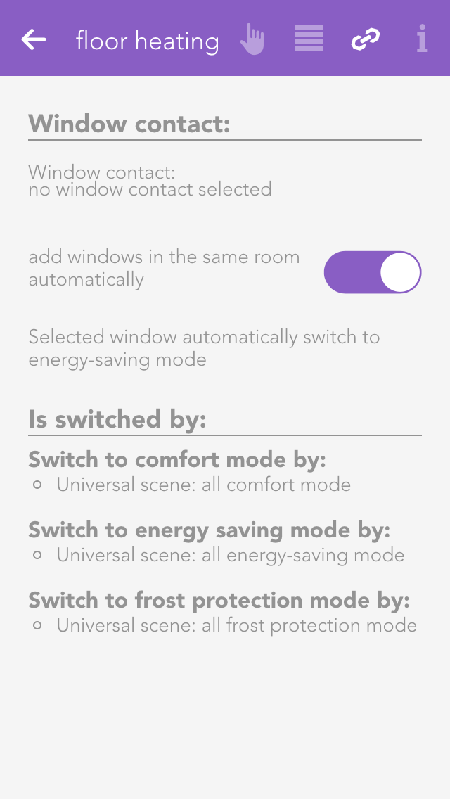
Links allow you to connect your room climate with other elements in your evon Smart Home.
Window contact
To ensure that heating is suspended when a window is open, you can add as many windows as you want via the button “add”. If one of these windows is opened, the heating will automatically enter into frost protection mode. As soon as the window is closed, comfort mode will be reactivated.
The settings for all room climate elements can be found under “all apps” –“settings” – “indoor climate”.
Can cool
If your heating system supports cooling, then you can activate this option. Warning! If your heating is not suitable for cooling, using this option could lead to malfunction. If in doubt, please contact a heating specialist.
Das Raumklima bietet folgende Auslöser für evon Smart Home Szenen (Wenn...):
Für Module bis zur Firmwareversion 3.x:
-- Geringe Luftfeuchtigkeit erkannt: Die konfigurierte minimale Luftfeuchtigkeit wurde unterschritten.
-- Hohe Luftfeuchtigkeit erkannt: Die konfigurierte maximale Luftfeuchtigkeit wurde überschritten.
-- Präsenz wurde aktiv: Präsenztaster am Raumbediengerät wurde gedrückt.
-- Präsenz wurde inaktiv: Präsenz wurde nach Ablauf der Präsenzzeit wieder inaktiv.
Für Module ab der Firmwareversion 4.0:
-- Geringe Luftfeuchtigkeit erkannt: Die konfigurierte minimale Luftfeuchtigkeit wurde unterschritten.
-- Hohe Luftfeuchtigkeit erkannt: Die konfigurierte maximale Luftfeuchtigkeit wurde überschritten.
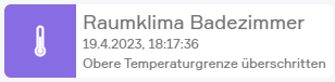
-- Obere Temperaturgrenze überschritten: Die konfigurierte minimale Temperaturgrenze wurde überschritten.
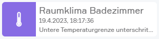
-- Untere Temperaturgrenze überschritten: Die konfigurierte maximale Temperaturgrenze wurde unterschritten.
-- Präsenz wurde aktiv: Präsenztaster am Raumbediengerät wurde gedrückt.
-- Präsenz wurde inaktiv: Präsenz wurde nach Ablauf der Präsenzzeit wieder inaktiv.
Das Raumklima bietet folgende Funktionen für evon Smart Home Szenen (Dann...):
- Auf Energiesparen umschalten: Der Status Energiesparen wird für den Heiz -/Kühlkreis aktiv und die Sollwerte für Energiesparen werden angewendet
- Auf Frostschutz umschalten: Der Status Frostschutz wird für den Heiz -/Kühlkreis aktiv und die Sollwerte für Frostschutz werden angewendet
- Auf Komfortbetrieb umschalten: Der Status Komfortbetrieb wird für den Heiz -/Kühlkreis aktiv und die Sollwerte für Komfortbetrieb werden angewendet
- Auf Modus Heizen umschalten: Der Modus "Heizen" wird aktiviert (Gerät muss von der globalen Heiz-/Kühlumschaltung ausgenommen sein)
- Auf Modus Kühlen umschalten: Der Modus "Kühlen" wird aktiviert (Gerät muss von der globalen Heiz-/Kühlumschaltung ausgenommen sein)
Das Raumklima bietet folgende Möglichkeiten für evon Smart Home Logiken:
Für Module bis zur Firmwareversion 3.x:
-- Ausgang aktiv: Hier können Sie ablesen, ob der Ausgang eingeschalten ist oder nicht.
-- Fehler: Hier können Sie ablesen, ob ein Fehler vorliegt.
-- Kühlen: Hier können Sie den Modus des Raumklimas steuern und ablesen. (Steuern ist nur möglich, wenn das Gerät von der globalen Heiz-/Kühlumschaltung ausgenommen ist)
-- Dauerhaft AUS: Dient zum permanenten ausschalten des Ausgangs.
-- Dauerhaft EIN: Dient zum permanenten einschalten des Ausgangs.
-- Automatikbetrieb aktiv: Hier können Sie ablesen, ob der Automatikbetrieb aktiv ist.
-- Energiesparbetrieb aktiv: Hier können Sie ablesen, ob der Energiesparbetrieb aktiv ist.
-- Frostschutzbetrieb aktiv: Hier können Sie ablesen, ob der Frostschutzbetrieb aktiv ist.
-- Komfortbetrieb aktiv: Hier können Sie ablesen, ob der Komfortbetrieb aktiv ist.
-- Heizanforderung aktiv: Hier können Sie ablesen, ob die Heizanforderung aktiv ist.
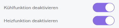
-- Heizfunktion deaktivieren: Dient zum Deaktiveren der Heizfunktion .
-- Kühlanforderung aktiv: Hier können Sie ablesen, ob die Kühlanforderung aktiv ist.
-- Kühlfunktion deaktivieren: Dient zum Deaktiveren der Kühlfunktion.
Für Module ab der Firmwareversion 4.0:
-- Ausgang aktiv: Hier können Sie ablesen, ob der Ausgang eingeschalten ist.
-- Heizfunktion deaktivieren: Dient zum Deaktiveren der Heizfunktion .
-- Kühlfunktion deaktivieren: Dient zum Deaktiveren der Kühlfunktion.
-- Luftfeuchtigkeitssensor vorhanden:Hier können Sie ablesen, ob ein Luftfeuchtigkeitssensor vorhanden ist.
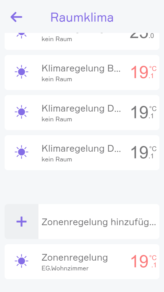
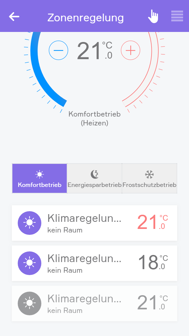
Mit Klimamodulen ab der Firmware Version 4.0 können die einzelnen Kanäle über eine Zonenregelung gesteuert werden.
Dies ermöglicht das einfachere Bedienen von Räumen welche mehrere Heiz- und/oder Kühlkreise besitzen.
Über "Zonenregelung hinzufügen" kann eine neue Zonenregelung erstellt werden.
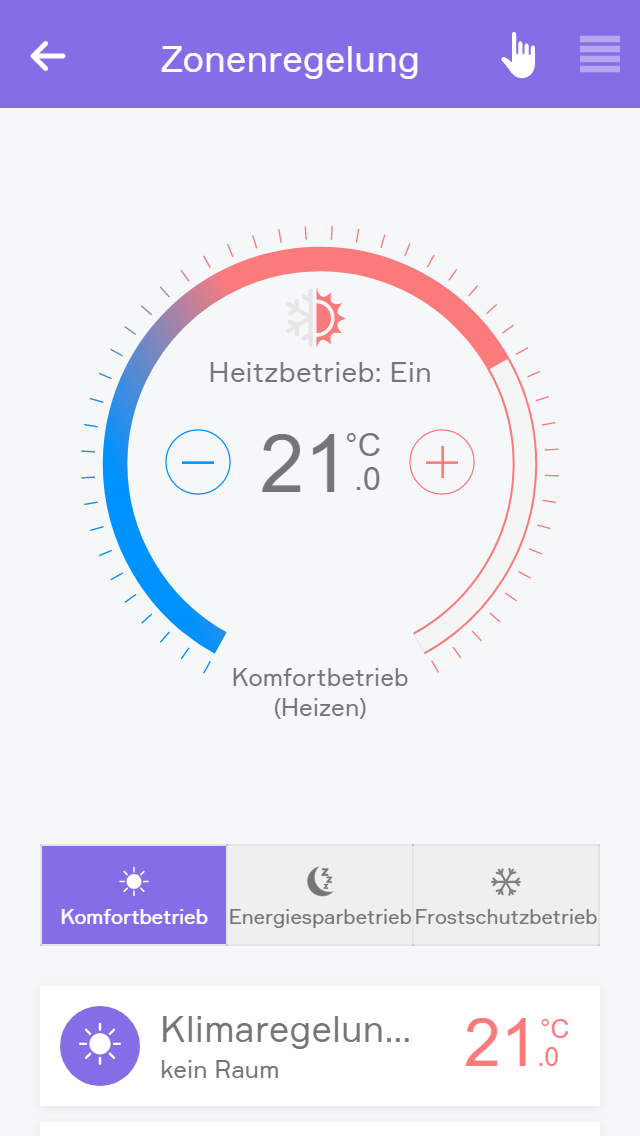
Im Operatorpanel kann über die drei nebeneinander liegenden Buttons die Betriebsart ausgewählt werden. Im Kreis oberhalb dieser Buttons können Sie die Solltemperatur anpassen über die Buttons “+” und “-” bzw. indem Sie auf die gewünschte Stelle im Kreis klicken. Diese werden dann auf alle verknüpften Raumklima Elemente übertragen.
Außerdem wird der aktuelle Status der verknüpften Raumklima Elemente angezeigt.
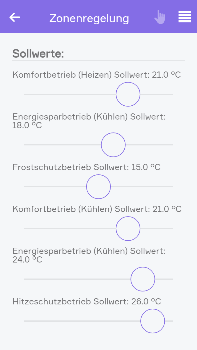
Im Parameterpanel kann ein Default Wert für die Sollwerte eingestellt werden. Diese werden dann auf alle verknüpften Raumklima Elemente übertragen.
Außerdem können hier Raumklima Elemente verknüpft werden.
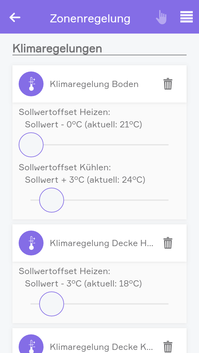
Pro Raumklima Element kann ein Sollwertoffset für Heizen und/oder Kühlen vergeben werden. Dieser passt die Sollwerte für das entsprechende Element an.
Ein Offset von 3°C beim Heizen, passt einen Default Sollwert von z.B. 21°C auf 18°C an, dadurch setzt die Heizung erst später ein. Beim Kühlen passt dieser den Sollwert von z.B. 21°C auf 24°C an.
Dadurch kann zum Beispiel erreicht werden, dass bei vorhanden sein einer Decken- und Bodenkühlung, zuerst die Deckenkühlung aktiviert wird. Sollte diese Kühlung nicht ausreichen und die Temperatur steigt weiter, wird auch die Bodenkühlung aktiviert.
Folgende Systemmeldungen können vom Raumklima ausgelöst werden:
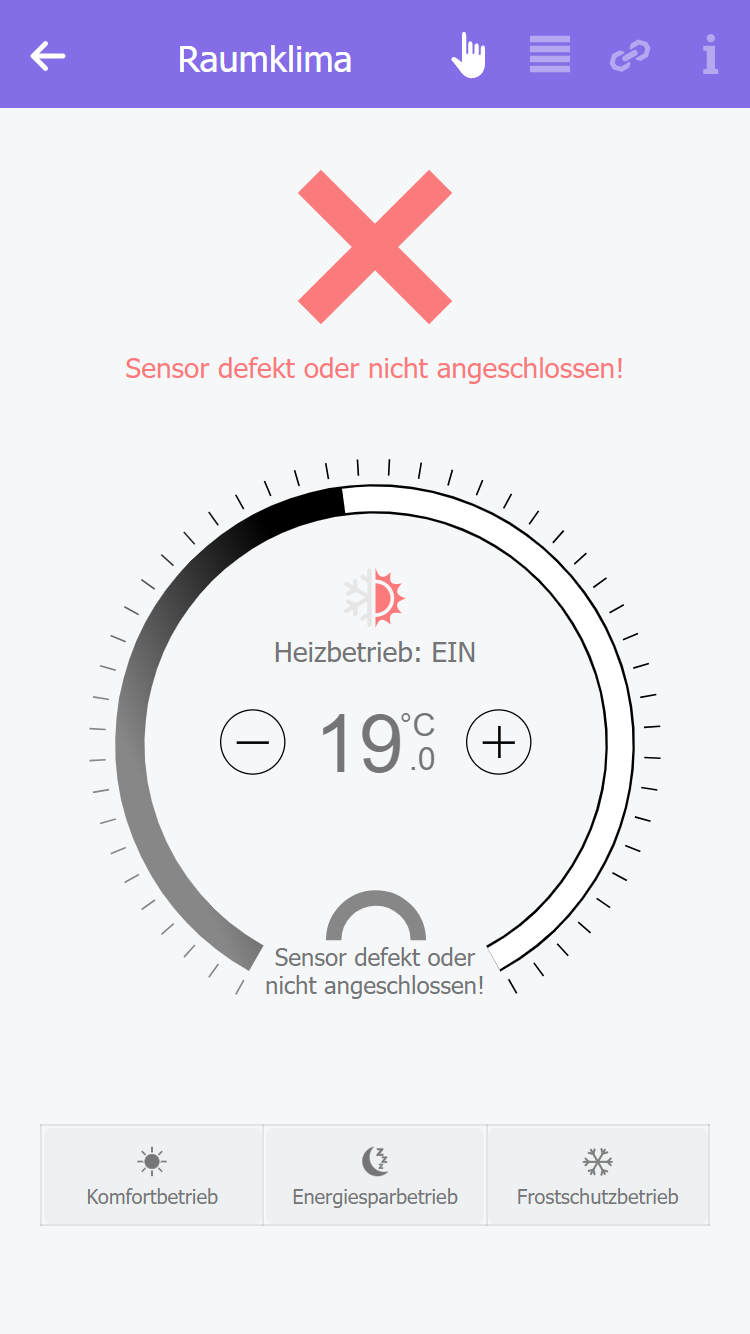
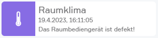
Das Raumbediengerät ist defekt! oder Sensor defekt oder nicht angeschlossen!
Dieser Fehler sagt aus, dass der Temperatursensor defekt, falsch oder gar nicht angeschlossen ist.
Dieser Fehler wird sofort erkannt, wenn keine oder ungültige Daten erhalten werden.
In diesem Zustand findet keine Regelung statt und das zugehörige Ventil ist dauerhaft geschlossen.
Es wird zudem eine Benachrichtigung ausgegeben, sobald dieser Fehler erkannt wurde.
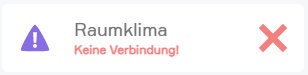
Im Object Panel wird als Status ein rotes X angezeigt und der Modus kann nicht geändert werden.
Im Operator Panel wird als Status ein rotes X mit dem Fehlertext angezeigt und die Bedienung ist deaktiviert.
Mögliche Fehlerursache ist eine falsche Verdrahtung oder ein defektes Raumbediengerät bzw. Temperatursensor.
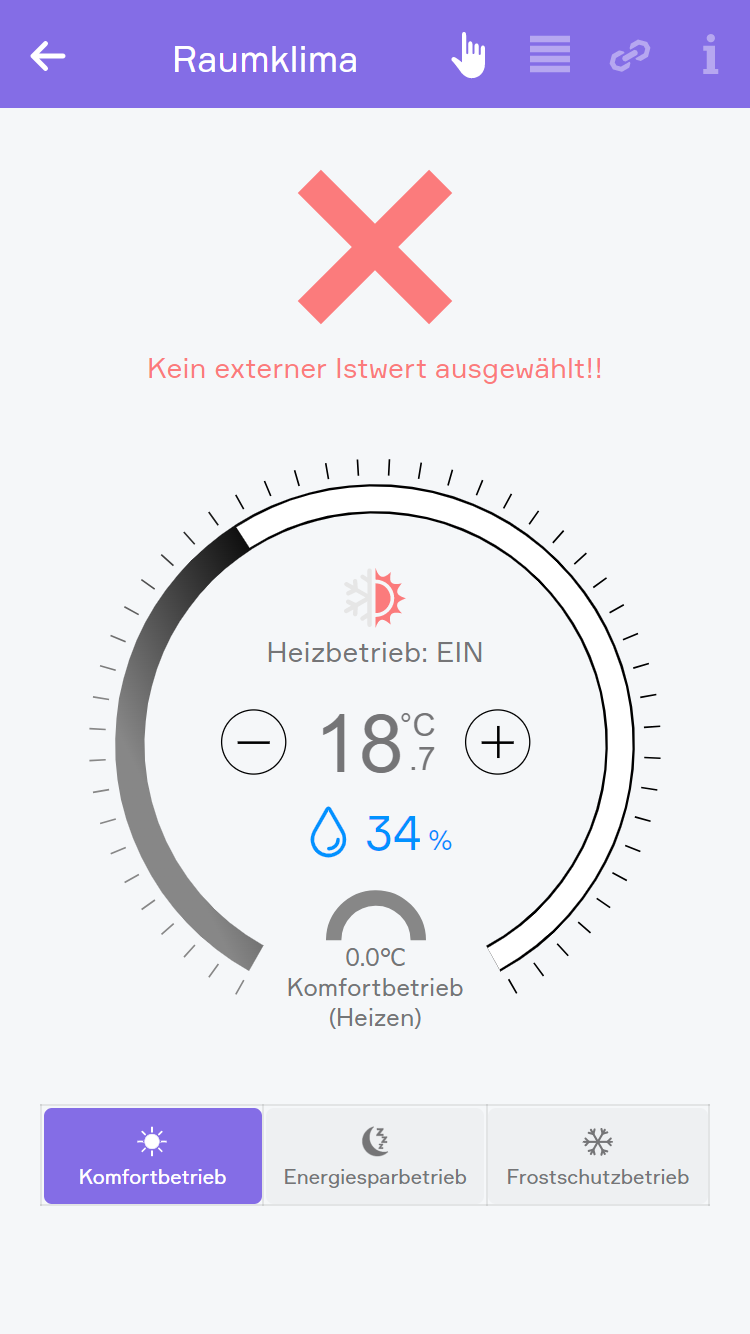
Kein externer Istwert ausgewählt
Dieser Fehler sagt aus, dass ein externer Istwert als Temperaturquelle erwartet wird, aber nicht verknüpft wurde.
Dieser Fehler wird sofort erkannt.
In diesem Zustand findet keine Regelung statt und das zugehörige Ventil ist dauerhaft geschlossen.
Im Object Panel wird als Status ein rotes X angezeigt und der Modus kann nicht geändert werden.
Im Operator Panel wird als Status ein rotes X mit dem Fehlertext angezeigt und die Bedienung ist deaktiviert.
Mögliche Fehlerursache ist, dass im Link Panel kein Externer Istwert verknüpft wurde oder bei Modulen mit der Firmware Version 4.x im Parameter Panel die Temperaturquelle entfernt wurde und keine neue hinzugefügt wurde.
Obere Temperaturgrenze überschritten
Dieser Warnung sagt aus, dass die Ist-Temperatur die obere Temperaturgrenze überschritten hat.
Diese Warnung wird sofort erkannt.
In diesem Zustand findet die Regelung wie gehabt statt.
Es wird zudem eine Benachrichtigung ausgegeben, falls die Option Benachrichtigen wenn Temperaturgrenzen unter- bzw. überschritten unter Benachrichtigungen im Parameter Panel aktiviert wurde.
Untere Temperaturgrenze unterschritten
Diese Warnung sagt aus, dass die Ist-Temperatur die untere Temperaturgrenze unterschritten hat.
Diese Warnung wird sofort erkannt.
In diesem Zustand findet die Regelung wie gehabt statt.
Im Object Panel wird als Status ein gelbes Rufzeichen angezeigt.
Im Operator Panel wird als Status ein gelbes Rufzeichen und ein Warntext angezeigt.
Es wird zudem eine Benachrichtigung ausgegeben, falls die Option Benachrichtigen wenn Temperaturgrenzen unter- bzw. überschritten unter Benachrichtigungen im Parameter Panel aktiviert wurde.
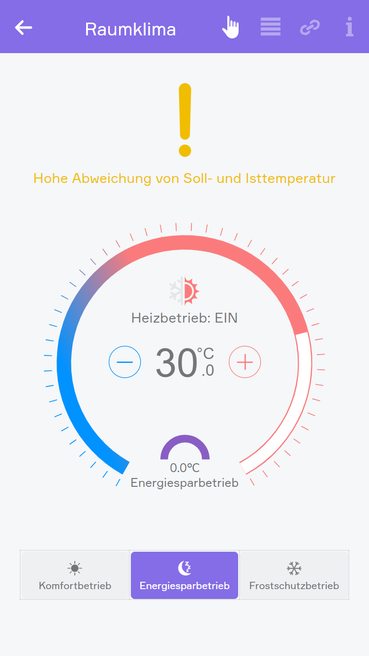
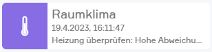
Heizung überprüfen: Hohe Abweichung von Soll- und Isttemperatur
Diese Warnung sagt aus, dass die Ist-Temperatur eine zu große Abweichung zur Soll-Temperatur hat.
Diese Warnung wird nach einer eingestellten Verzögerung erkannt, welche im Parameter Panel unter Benachrichtigungen und Dauer eingestellt wurde.
Diese Warnung wird angezeigt, wenn Kühlfunktion deaktivieren und Heizfunktion deaktivieren nicht aktiviert sind.
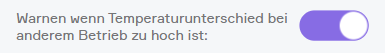
Diese Warnung wird angezeigt, wenn die Optionen Warnen wenn Temperaturunterschied bei anderem Betrieb zu hoch ist und Kühlfunktion deaktivieren aktiviert sind und der Modus in Einstellungen Raumklima auf Kühlen gestellt ist.
Diese Warnung wird angezeigt, wenn die Optionen Warnen wenn Temperaturunterschied bei anderem Betrieb zu hoch ist und Heizfunktion deaktivieren aktiviert sind und der Modus in Einstellungen Raumklima auf Heizen gestellt ist.
In diesem Zustand findet die Regelung wie gehabt statt.
Im Object Panel wird als Status ein gelbes Rufzeichen angezeigt.
Im Operator Panel wird als Status ein gelbes Rufzeichen und ein Warntext angezeigt.
Es wird zudem eine Benachrichtigung ausgegeben, falls die Option Benachrichtigen wenn Temperaturunterschied zu hoch unter Benachrichtigungen im Parameter Panel aktiviert wurde.
Gesperrt
Dieser Status sagt aus, dass die Regelung gesperrt ist.
Dieser Status wird sofort erkannt, sobald einer der nachfolgenden Zustände eintrifft:
In diesem Zustand findet keine Regelung statt und das zugehörige Ventil ist dauerhaft geschlossen.
Im Object Panel wird die Temperatur und darüber ein Sperrzeichen angezeigt und der Modus kann nicht geändert werden.
Im Operator Panel wird als Status Gesperrt angezeigt.
Im Parameter Panel wird falls ein Sperrkontakt verknüpft wurde, dieser unter Sperrkontakt angezeigt.
Mögliche Ursachen der Sperre sind:
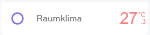
Dauerhaft EIN
Dieser Status sagt aus, dass das zugehörige Ventil dauerhaft komplett geöffnet ist.
Dieser Status wird sofort erkannt, sobald die Option Dauerhaft EIN im Parameter Panel aktiviert wurde.
In diesem Zustand findet keine Reglung statt, das zugehörige Ventil ist dauerhaft komplett geöffnet.
Im Object Panel wird ein Kreis angezeigt und der Modus kann nicht geändert werden.
Im Operator Panel wird als Status Dauerhaft EIN angezeigt.
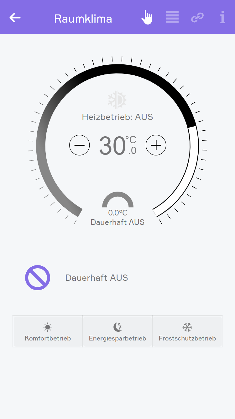
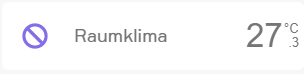
Dauerhaft AUS
Dieser Status sagt aus, dass das zugehörige Ventil dauerhaft komplett geschlossen ist.
Dieser Status wird sofort erkannt, sobald die Option Dauerhaft AUS im Parameter Panel aktiviert wurde.
In diesem Zustand findet keine Regelung statt und das zugehörige Ventil ist dauerhaft geschlossen.
Im Object Panel wird ein durchgestrichener Kreis angezeigt und der Modus kann nicht geändert werden.
Im Operator Panel wird als Status Dauerhaft AUS angezeigt.
A few inputs and outputs in evon Smart Home are used similarly in different modules. This is described in this section.
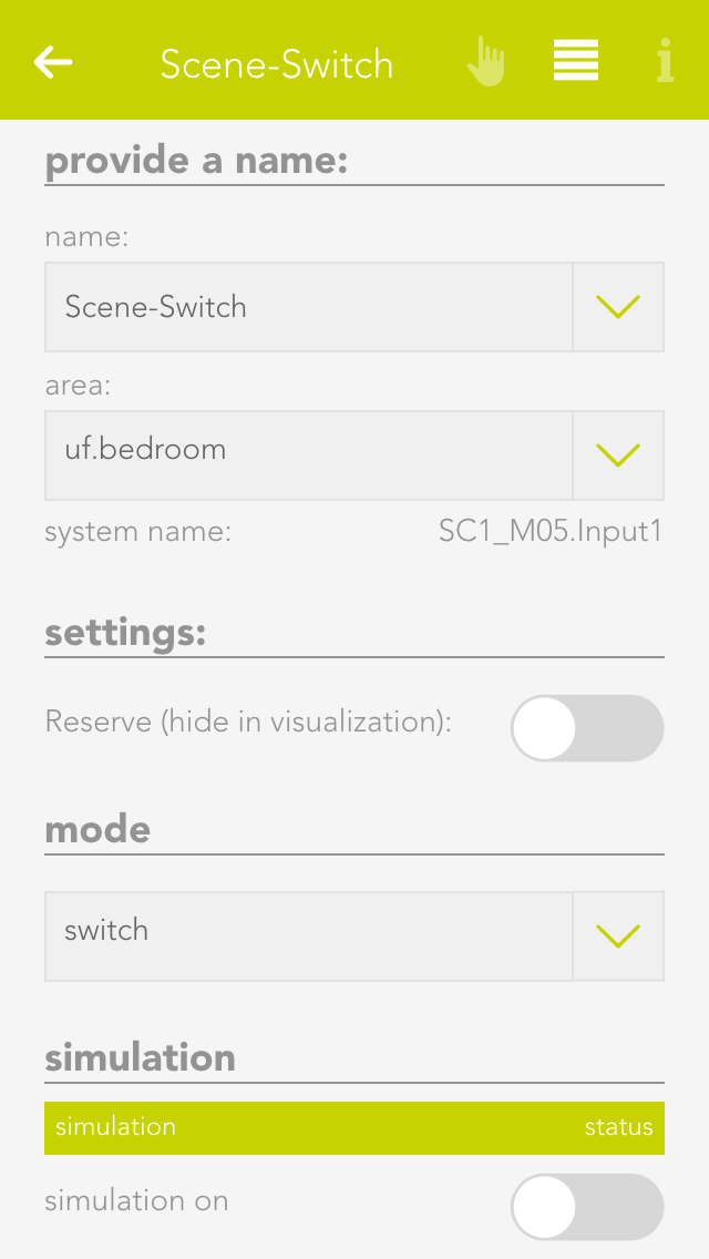
A switch can be connected to a light module, blind module or a digital module. A switch has a pre-defined function for a light or blind module. Every switch can be simulated in evon Smart Home for test purposes.
These switches can be found under “all apps” – “switches”.
Naming
If you have connected your switch to a light or shading module, then the switch is automatically named according to the light or blind. If you wish to give it a different name, then deactivate the option “same name as blind/light” in the parameter panel and give the switch a new name. If you have connected your switch to a digital module, then you must name it yourself.
Reserve
If you have a switch in your system that you don’t use, then you can hide it by deactivating the option “reserve “hide in display” in the app “ switches”. To unhide it, you can find your switch in the app “hardware”.
Mode
If you want to change the mode, i.e. define the switch as a presence detector or a digital input, then you can do this in the parameter panel under “mode”. Not every module can change the mode however, or not all possibilities are available. This means that the light modules’ switch can only be converted to a presence detector. Switches for a blind element cannot be converted. Switches for digital modules have all three modes.
If you have linked a switch to a scene and would now like to simulate this scene, then there is no need to go to the switch and press it every time, you can use simulation to create the switch press. Simply activate the option “simulation” in the operator panel to see 3 buttons that you can use to simulate switch presses.
Warning: If you leave the simulation mode activated, the autonomous functions will not work!
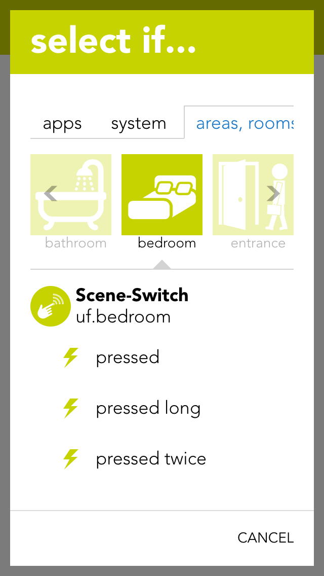
You can use the switches for a scene (assuming it as been named). In the scene “if …” just select the switch and decide if you want the scene to be executed after a single, double or long press.
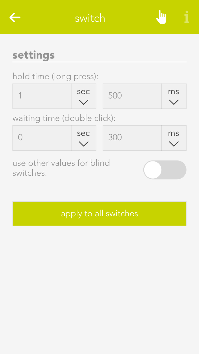
Open the switches settings (“all apps” – “settings” – “switches”) if you want to define the times for a press and double-press. Select the desired values and confirm them by clicking the button “use values for all switches”.
Hold time (long button press)
A switch must be pressed for at least thus time to be recognized as a long button press.
Wait time (double-press)
The gap between two switch presses must be as least as big as the defined wait time to be recognized as a double-press.
If you wish to define different values for a switch that is connected to a blind module, then activate the option “use other values for blinds”.
A motion detector can be connected to a light module or a digital module. The motion detector has a pre-defined function when connected to a light module. Motion detectors can be simulated in evon Smart Home for test purposes.
You can find motion detectors under “all apps” –“motion detectors”.
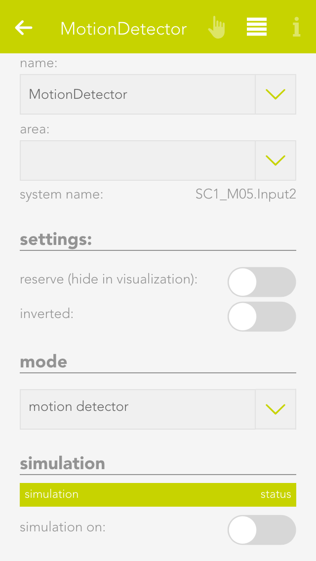
Naming
If you have connected a motion detector to a light module, then it is automatically assigned the same name as the light. If you wish to assign a different name, then deactivate the option “same name as light” in the parameter panel and enter the name you wish. If the motion detector is connected to a digital module, then you must assign it a name yourself.
Invert
If the motion detector is connected to a digital module, you have the possibility to invert the logic by activating the option “invert” in the operator panel.
Reserve
Should you have a motion detector in the system that you do not use, you can hide in from the app “motion detector” by activating the option “reserve (hide in display)” in the parameter panel. To unhide it, you will find your movement detector in the app “hardware”.
Mode
If you wish to change the mode, i.e. convert the motion detector input to a switch or a digital input, you can do this by changing the mode for the motion detector in the parameter panel. Not all modes can be changed in all modules, or not all possibilities are available. This means that a motion detector for a light module can only be changed into a button. All three modes are available for motion detectors for a digital module.
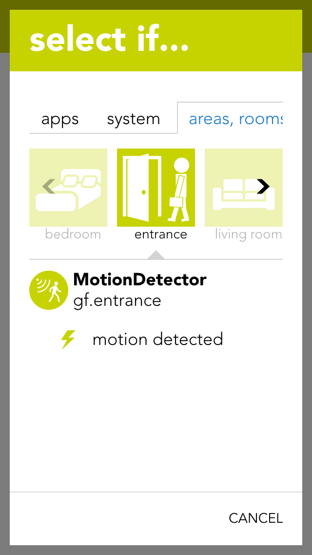
You can also use the motion detector for a scene (in as far as it has been named). In the scene, select the motion detector for “if …” and decide if you want the scene to be carried out on the rising or falling edge of the signal.
Rising edge
The electrical contact of the motion detector has been activated.
Falling edge
The electrical contact of the motion detector has been deactivated (after the internal time of the motion detector).
For example, if you have linked a motion detector to a scene and you would like to test this scene, then you do not have to go to the motion detector and activate it every time, you can change the state using simulation. Simply activate the option “simulation on” in the operator panel to see the option with which you can change the state.
Warning, if you leave the simulation switched on, the autonomous function will not work!
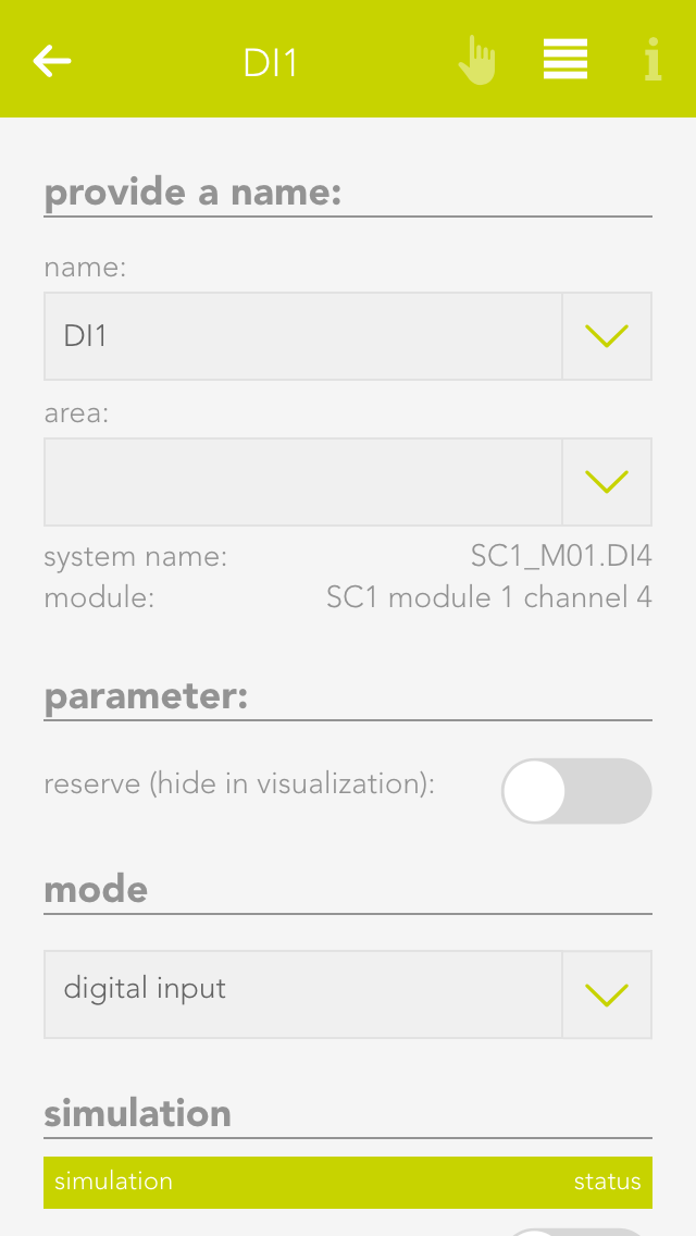
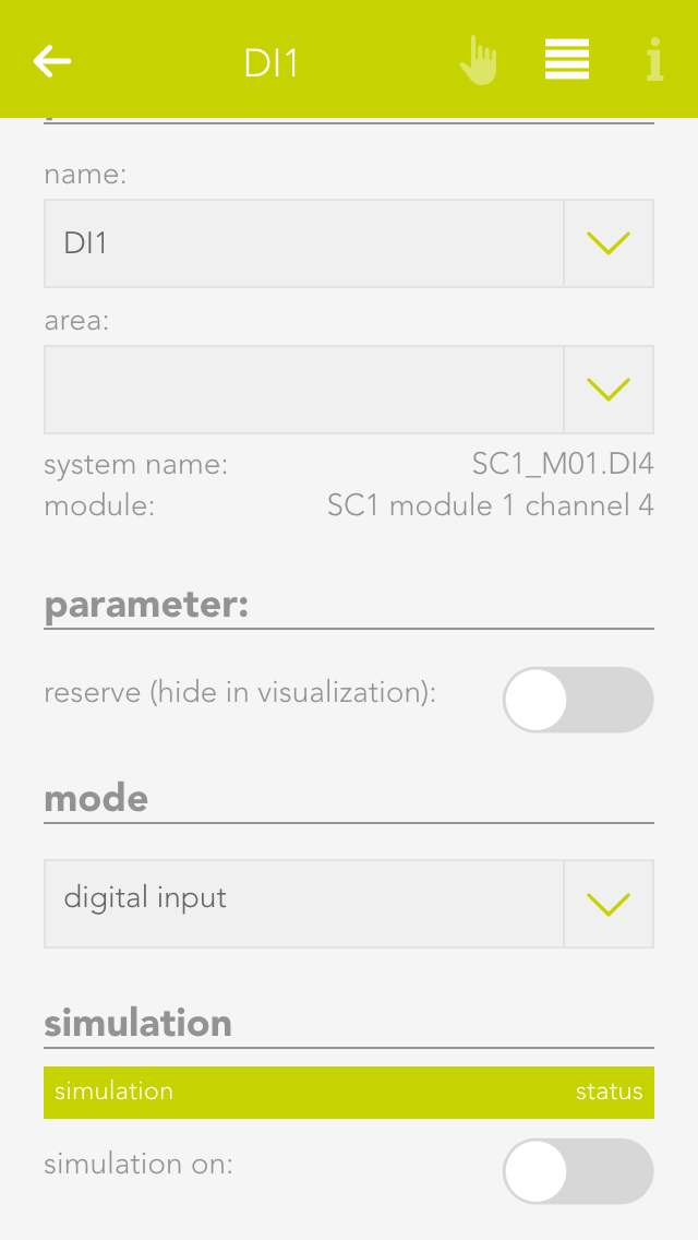
You can use a digital input for functions not provided by any evon Smart Home function module. You can name each digital input and simulate then for test purposes.
You can find the app “digital inputs” under “all apps” – “digital inputs”.
Reserve
If you have a digital input in your system that you are not using, you can activate the option “reserve (hide in visualization) to hide this digital input in the app “digital inputs”. (To unhide this, the digital input can be found in the hardware app)
Mode
If you wish to change the mode, i.e. convert a digital input into a button or a movement detector, this can be done in the parameter panel for the digital input under “mode”.
If you have connected a digital input to a scene and would like to test the scene, you do not have to navigate to the digital input and activate it every time, you can change it directly via simulation. To do this, activate “simulation on” in the operator panel to see the option “simulation value” with which you can change the state. Warning, once the simulation has been activated, the autonomous function will no longer work! Any changes in the state of the input “hardware” will be overwritten by the simulation.
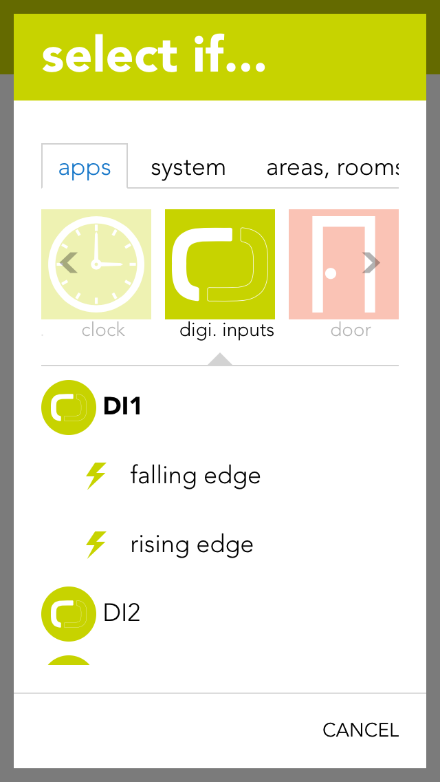
You can also use a digital input for a scene (in as far as it has been named). Select the digital input in the scene’s “IF ….” and decide whether you want the scene to be carried out on the rising or falling edge.
Rising edge
The electrical contact of the digital input has been closed.
Falling edge
The electrical contact of the digital input has been opened.
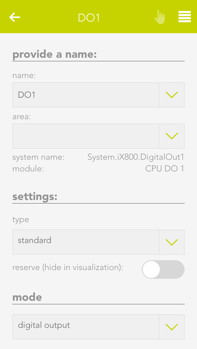
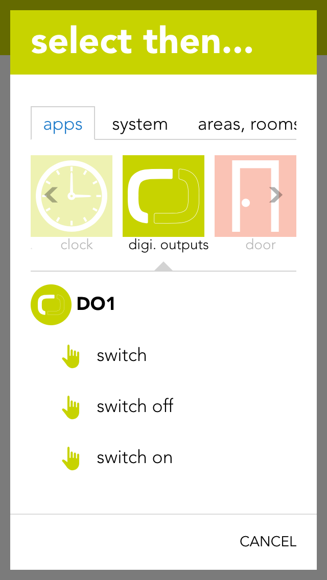
The app “digital outputs” provides you with an overview of all digital outputs in your system. This is where you can name them and change the state of the outputs.
The app “digital outputs” is located under “all apps” – “digital outputs”.
You have two possibilities to change the state of a digital output. Either you can click on the power symbol on the left in the object panel or you can click on the button “switch” in the operator panel.
You can give a name to a digital output in the parameter panel and optionally allocate it to a room.
Save output if bus fault
If the output is active when the bus connection to the CPU fails (for example if the 24V power supply to the module fails), this option lets you guarantee that the active remains activated even in a fail state. If this option is not activated, then the output is reset after every bus connection failure.
In safety-critical controllers, it should be carefully examined whether this function should be activated, since this output is kept active if the system fails.
Mode
With the mode setting, you can change the behavior of the output once it is active. The following options exist:
Standard
This ist the normal setting for a digital output. With this, the output stays active until the signal ends.
Minimum on duration
With this mode, the output stays active for at least the specified time, even when it is deactivated before.
Pulse
In this mode, the output will automatically be deactivated after the defined timeframe.
Reserve (hide in visualization)
If you have a digital output in your system that you do not use, then you can hide this digital output in the digital output app by activating the option “reserve (hide in visualization)” (located in the parameter panel). (To unhide, the digital output can be found in the hardware app).
Change mode
If you wish to change the mode, i.e. convert a digital output to a socket, then you can do this by changing the mode for the digital output in the parameter panel.
You can also use a digital output for a scene (in as far as it has been named). In the scene’s “if …” simply select the digital output to see the following possibilities:
Switch off
The digital output is switched off.
Switch on
The digital output is switched on.
switch on for
The digital output will be switched on for a defined amount of time.
Toggle
The state of the digital output is toggled.
The app “sockets” provides an overview of all sockets in your system and allows you to name them and change their state.
The app “sockets” can be found under “all apps” – “sockets”.
You have two possibilities to change the state of a socket. Either you can click on the power symbol on the left in the object panel or you can click on the button “toggle” in the operator panel.
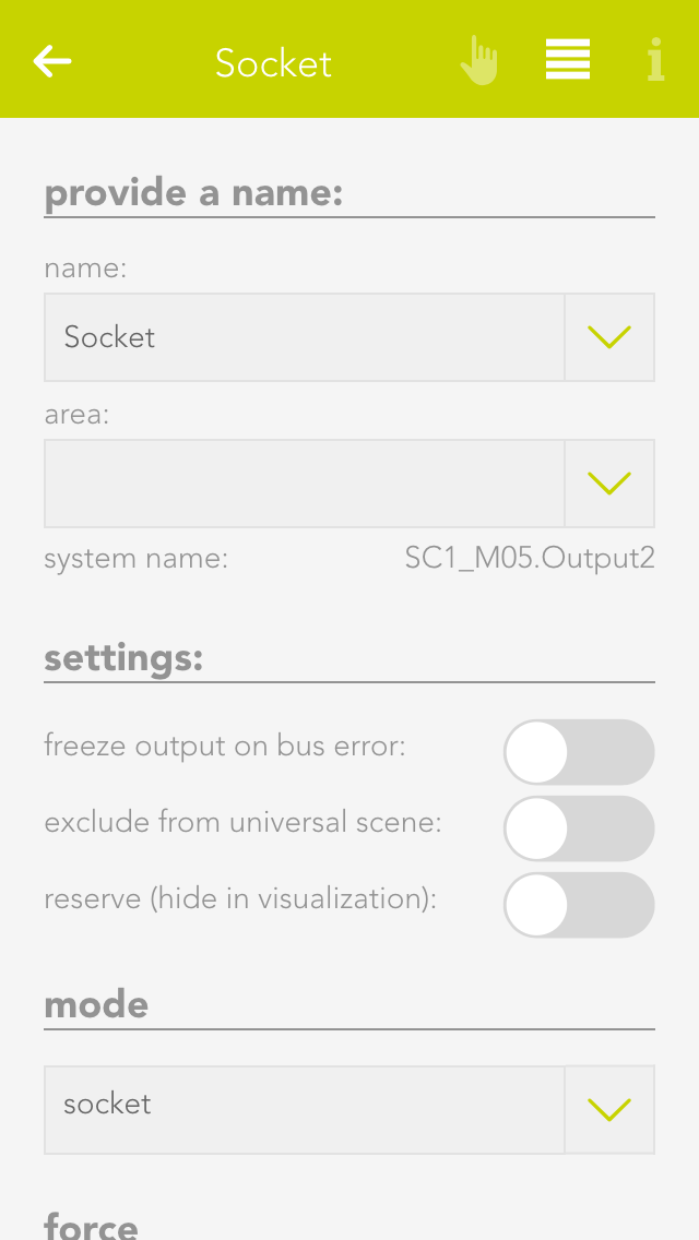
The parameter panel lets you give the socket a name and optionally allocate it to a room.
Save output if bus fault
If the socket is currently active and the bus connection to the CPU fails (e.g. the 24V power supply to the module fails), then activating this option will guarantee that the socket remains active even in a fail state. If this option is not activated, then the socket is reset after every bus connection failure.
In safety-critical controllers, it should be carefully examined whether this function should be activated, since this output is kept active if the system fails.
Reserve (hide in visualization)
If you have a socket in your system that you do not user, you can hide this socket in the app “sockets” by activating the option “reserve (hide in visualization) (located in the parameter panel). (To unhide, the socket can be found in the app “hardware”).
Change mode
If you want to change the mode, i.e. convert socket to a digital output, then this can be done by changing the mode in the socket’s parameter panel.
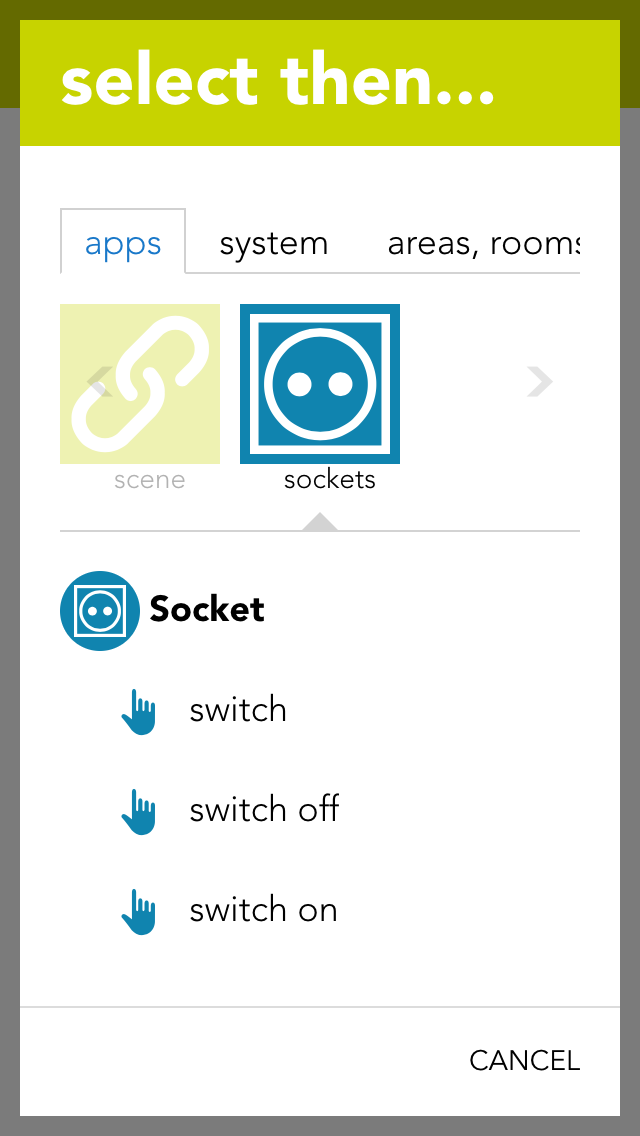
The socket can be used for a scene (in as far as it has been named). In the scene’s “if….”, select the socket and one of the following possibilities:
Switch off
The socket is switched off.
Switch on
The socket is switched on.
Switch on for
The socket is switched on for the time you define.
Toggle
The status of the socket is toggled.
An analog input can measure voltage in the range 0-10V. This voltage is then scaled to the range defined by the user. This value can be used by the user for calculations (using logic), or simply to trigger scenes if the value exceeds or falls below certain (definable) limits.
The analog inputs are located under “all apps” – “analog inputs”.
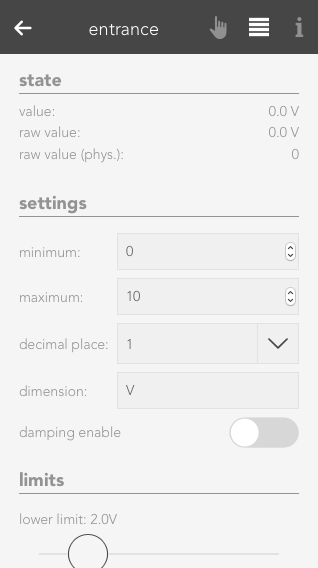
Minimum/Maximum
Minimum and maximum limits of the measured value. These inputs must be taken from the description of the sensor used. For example, you wish to measure the humidity in a room and use a sensor with a 0-10V output signal. The sensor documentation tells you that the sensor can measure humidity from 0% to 100%. The minimum limit is hence 0 and the maximum limit is 100.
Number of decimal places
Indicates the number of decimal places used to calculate the value.
Dimension
This is where you define exactly what you wish to measure with this analog input (e.g. temperature °C).
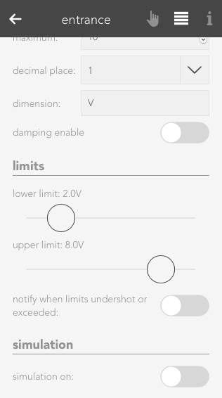
Notification on limit violation
If the value of the analog input falls below the lower limit or exceeds the upper limit, then you will be notified by the system if this checkbox is activated.
Upper limit
Enter the upper limit here. If the value exceed this limit, you can react with a scene by selecting the trigger for “value above upper limit” in the “IF …” statement.
Lower limit
Enter the lower limit here. If the value falls below this limit, you can react with a scene by selecting the trigger for “value below upper limit” in the “IF …” statement.
Der Analoge Eingang bietet folgende Auslöser für evon Smart Home Szenen (Wenn...):
Raw value
A raw value is the voltage (0-10V) measured on the input of the module.
Raw value (phys.)
Corresponds to the output of an analog/digital converter and is used for the calculation into the physical measured value.
Value
Corresponds to the scaled value resulting from the raw value, minimum and maximum.
Value = (Raw value phys. / Raw value phys. MAX) * (Maximum – Minimum) + Minimum.
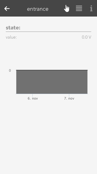
The Operatorpanel of the selected Analog Input also provides you with a chart, which keeps track of the measured values.
If you wish to simulate the value for an analog input, this is easily done by activating the option “simulation on” in the operator panel and selecting the desired value in the slider. This can be useful if you have defined a scene you wish to be carried out if a limit is exceed and you wish to test what happens.
An analog output outputs voltages in the range 0-10V. To do this, enter a value in your defined area and this will be output as a voltage between 0-10V.
The analog outputs can be found under “all apps” –“analog output”.
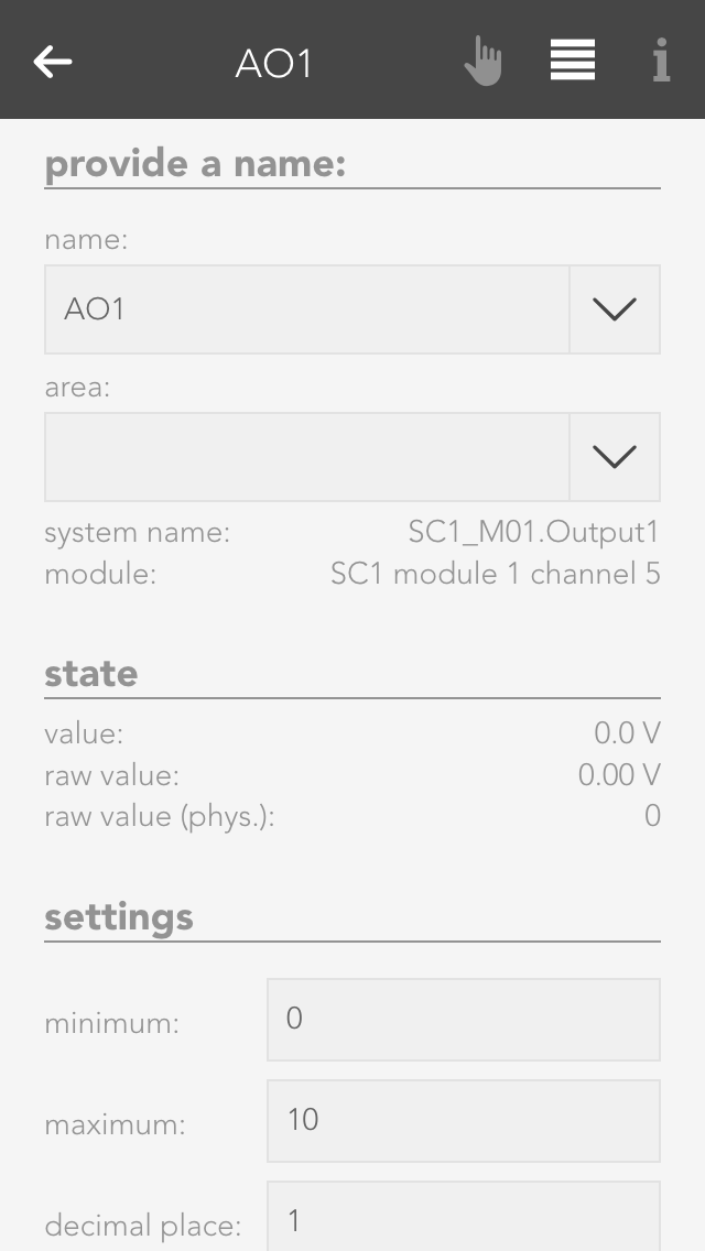
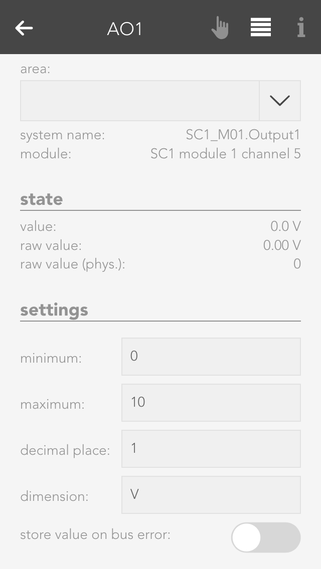
Minimum/Maximum
The calculated value is in the range between the minimum and maximum. This means that if 10V are meant to be present on the module output, then the value must be set to the defined maximum value (100%).
Number of decimal places
Defines the number of decimal places for the calculation.
Dimension
Define here what you wish to control with this analog output (e.g. speed: %)
Stored value upon bus error
If the control were to fail, the last value would be stored if you have activated this option. If you did not activate this option, the value present when the control failed will be lost.
Der Analoge Ausgang bietet folgende Funktionen für evon Smart Home Szenen (Dann...):
Raw value
The raw value is the voltage 0-10 V that is present (set) on the output of the module.
Raw value (phys.)
This is the digital value sent to the module.
Value
This is the scaled value that has been converted to the defined range between minimum and maximum, with the defined number of decimal places and the defined dimension.
There are two different possibilities to set a value to the analog output. Either you set the value via the operator panel for the analog output, or you select the analog output in a scene for the “if …” statement and then select “write value”. Then you can change the value by clicking on the pencil.
You can view all the module channels to which you can connect temperature sensors (e.g. PT1000) in the app “temperature”.
The temperature sensors can be found under “all apps” – “temperature”.
With module A1240, you can only set the temperature limits (as described in the item “scene” above). This module can only accept temperature sensors of type PT1000.
If you posses a module of type A1380, you can connect temperature sensors of type PT1000, KTY81-110 and KTY81-210. To ensure that the modules know which sensor has been connected, you must navigate to the parameter panel for this temperature sensor and select the type under “mode”.
If you want to know what happens if the temperature rises above or falls below a certain value, then you don’t need to cool or heat the temperature sensor. You can use the option “simulation” in the operator panel. Simply activate the checkbox “simulation on” and enter the desired temperature in the input field that appears. Warning, do not forget to deactivate the simulation when you have finished testing.
Hier werden Dir einige Beispiele beschrieben wie Du einen Temperatursensor verwenden kannst.
Outside temperature
If you want a temperature sensor in your system to determine the outside temperature, you need to add it using the button “add” in the global settings under the item “outside temperature” and drag it to the first position. (More information in this in the documentation for global settings).
External current value for room climate zone
If you want to use this temperature sensor as an actual value for a room climate zone, then you must set the mode to “external actual value” in the desired room climate zone under “settings” and then connect the temperature sensor with it (more detail in the chapter “room climate”).
Scene
In order to link a temperature sensor with a scene, you must first allocate a name to it. Then you can set an upper and a lower temperature limit in the parameter panel that you can use in the scene for the “if …” statement. You can create a scene for the temperature falling below the lower limit or rising above the upper limit.
Logic
If you are an expert with the app “logic”, you can also use this temperature sensor here by connecting the input of a logic element with the current temperature reading.
Die Temperatur App bietet folgende Auslöser für evon Smart Home Szenen (Wenn...):
- Obere Grenze überschritten: Das konfigurierte obere Temperaturlimit wurde überschritten
- Untere Grenze unterschritten: Das konfigurierte untere Temperaturlimit wurde unterschritten
Durch die Umwandlung von digitalen Ausgängen zu Lüfter können diese beispielsweise für die Ansteuerung von WC Lüfter verwendet werdenDiese Lüfter reagieren automatisch auf Lichter desselben Raums oder optional auf Taster oder Bewegungsmelder.
Sie finden die Lüfter unter „Alle Apps“ – „Lüftung“
Um einen Lüfter zu erstellen können Sie einen beliebigen digitalen Ausgang verwenden. Öffnen Sie dazu das Operator Panel des gewünschten digitalen Ausgangs und ändern Sie den Typ auf "Lüfter". Der digitale Ausgang wird automatisch zu einem Lüfter umgewandelt und ist unter Lüftung zu finden.
Durch das Auswählen eines Raumes werden automatisch alle im Raum befindlichen Lichter mit der Lüftung verknüpft. Sie haben jedoch jederzeit die Möglichkeit, Lichter zu entfernen oder hinzuzufügen. Zusätzlich haben Sie die Möglichkeit, Bewegungsmelder und Taster zu verknüpfen.
Einschaltverzögerung:
Beim Einschalten des ersten verknüpften Lichtes, bzw. der ersten Betätigung eines verknüpften Tasters oder der ersten Aktivierung eines verknüpften Bewegungsmelders wird die Einschaltverzögerung aktiviert. Nach Ablauf der Einschaltverzögerung wird der Lüfter eingeschaltet.
Ausschaltverzögerung:
Nach dem Ausschalten des letzten verknüpften Lichtes, bzw. der nach der letzten Betätigung eines verknüpften Tasters oder der Deaktivierung des letzten Bewegungsmelders wird die Ausschaltverzögerung aktiviert. Nach Ablauf der Ausschaltverzögerung wird der Lüfter ausgeschaltet.
Im Operator Panel sowie im Object Panel haben Sie die Möglichkeit, den Lüfter zu steuern.
Durch das manuelle Einschalten des Lüfters wird der Lüfter sofort eingeschaltet und die Ausschaltverzögerung aktiviert. Nach Ablauf der Ausschaltverzögerung wird der Lüfter wieder ausgeschaltet.
Durch erneutes Einschalten des Lüfters, während die Ausschaltverzögerung aktiv ist, wird die Ausschaltverzögerung wieder zurückgesetzt.
Durch das manuelle Ausschalten wird der Lüfter sofort ausgeschaltet.
Der Lüfter bietet folgende Funktionen für evon Smart Home Szenen (Dann...):
The general settings for your evon Smart Home can be found under “all apps” – “settings”.
This is where you determine whether you have Internet access to your evon Smart Home. If external access is active, then you can access your evon Smart Home using your evon Smart Home ID from anywhere.
Global settings let you define what is responsible in your evon Smart Home for activating wind, rain, frost, dusk states. For example, if you have connected a rain sensor, this is where you would find the settings for your system to display whether it is raining or not. The global settings can be found under “all apps” – “settings”.
You can connect the rain sensor to the appropriate input of the iX800 controller. IF you also have a weather station or Internet weather, then you need to select which element invokes “rain” in the system. Simply drag the box with the text “iX800” in the item rain to the first place (if more than one box is available) to be able to use the controller’s rain sensor input.
If you have connected your rain sensor to a digital input, then you can select it using the button “add” and drag it to the first position.
The dusk sensor can be connected to the dusk input on the iX800 controller. If you also have a weather station or Internet weather, then you need to select which element invokes “dawn/dusk” in the system. Simply drag the box with the text “iX800” in the item dusk to the first position (if more than one box is available) to use the dusk input on the controller.
If you have connected your dusk sensor to a digital input, then you can select it via the button “add” and drag it to the first position.
Connect your wind contact to the wind input on the iX800 controller. If you also have a weather station or Internet weather, then select which element invokes “wind alarm” in your system. Drag the box with the text “iX800” in the item wind to the first position (if more than one box is available) to use the wind contact on the controller.
If you have connected your wind contact to a digital input, then select it using the button “add” and drag it to the first position.
You can select the value you wish to use for the outside temperature by dragging the element to the first position in the item outside temperature.
If you wish to measure the outside temperature using a sensor, you can do this by clicking the button “add”.
In addition, you can define a value for the frost and heat warning (in the parameter panel). As soon as the outside temperature rises above or below this value, a scene or a notification will be invoked.
The sunrise and sunset times can be calculated using the geo-coordinates. These times are then used for the dawn/dusk calculations. To make sure that the dawn/dusk calculation is performed using the geo-coordinates, drag it to the first position in the item dawn/dusk.
The geo-coordinates can be entered using the decimal point format. To find out which geo-coordinates your house has, simply go to www.maps.google.at and search for your house. Right-mouse click on your location and select “what is here?” to display your geo-coordinates (the first value is north and the second east).
If you wish to change the calculated times then activate the option “adjust time for dawn/dusk”. This will let you adjust how many minutes earlier or later you wish dawn and dusk to be.
If you wish to simulate what happens if it rains, for example, then you can simply simulate the occurrence of rain by activating the option “simulate rain” in the item “rain” and then activate the option “rain on”. This is also true for wind, outside temperature and daylight. Warning, do not forget to end the simulation when you no longer need it (e.g. deactivate “rain simulation”).
You can define which events for you would like to receive notification of in the parameter panel.
The updates screen lets you make sure your evon Smart Home is up-to-date. Simply click the button “search for updates” and if an update is available, click “execute update”. If you wish your system to automatically search for updates, activate the setting “search for updates automatically” in the operator panel. You can also see the current version and the time of the last update and the update channel here.
Furthermore, you can create recovery points, which allow you to reset your evon Smart Home to an earlier state if you have inadvertently maladjusted parameters. Such recovery points are recommended once you have named all your lights, blinds, etc. and have set them up as you require. Use the button “reset to factory setting” to reset your evon Smart Home to the original factory settings.
Saved recovery points will be shown in a list, where you can delete, recover, or download them at any time.
You can create one recovery point per day. If you create more, only the last one will be saved. In addition, you can also restore your system with a downloaded recovery file by using the button 'restore local restore point'.
A recovery point of your current configuration is created automatically before every update.
Project name
You can give your evon Smart Home any name you like in the system settings.
Controller new start
This function restarts your system. Note that while the system is restarting, you do not have a connection to the CPU.
Manifest
This item shows you whether your visualization is up-to-date. The setting “automatic reload” lets you update your visualization automatically if it is not up-to-date.
All information pertaining to your system can be found under the item system diagnostics, such as current version, memory used, IP address, etc.
You can also look at cycle times. This is an indication of the load on your evon Smart Home system. You can also see the last five peak values. The cycle time is the time required for a complete run of the program.
“Time” lets you see the current time and date used in your controller (server time), the time zone your controller is in and the time of the device you have used to connect to your evon Smart Home (mobile phone, tablet …).
The time zone lets you allocate the desired time zone to your controller. The item “set time” allows you to set the time in the controller. The button “use client time” allocates the time used by your device (mobile phone, tablet) to the controller. The button “set time manually” lets you set the time and the date for your controller yourself.
This area contains all network settings for the network used by your evon Smart Home. You can also configure whether the IP address and DNS server should be automatically allocated, or whether you wish to define them yourself.
This app lets you send email notifications via an existing email account. The “test mail” function is used to test the configured settings. You will need to obtain the required settings for the SMTP server from your email provider.
You can either send a test email or you can select “send email” in the “system” tab in a scene “if …” statement. Then all you need to do is enter the sender, recipient, subject and text.
If you wish to register with your Gmail account, then you must allow “less secure apps” in your Gmail account. Simply open the link to the Google Config and click “activate”.
You can edit the pre-defined names in the dictionary. These names will be suggested to you when you wish to name a light, a blind, etc. However, you can even select a different name when naming your elements. The names in the dictionary are only a guide.
The “devices” app shows you all mobile devices that have been registered in your system.
The “devices” app is under “all apps” – “settings” – “devices”.
If you open a device, the display shows you the name and model of the device in the operator panel. The parameter panel shows detailed information concerning the device.
If you wish to receive notifications on this device (e.g. window is open), then you need to activate the checkbox “receive push notifications”.
The hardware app lists all modules that are connected to your system. If you wish to obtain a list of module channels, then all elements in this module are clearly displayed and in the correct order, the way they are connected to the module. This view can make it much simpler for you to name the individual elements, since you immediately know which module and which channel you wish to name.
The hardware app is located under “all apps” – “hardware”.
Hierarchically above the modules, you can see which line the module is located in (e.g. SC1 – line 1).
Wenn Sie die TechCOM-Linie öffnen, sehen Sie die Anzahl der verbundenen Module und können nach neuen suchen.
If you open the line, the first thing you will see at the top is general information about the line. The item “cycle time” lets you define the cycle time for your bus line (standard is 200 ms). “Required cycle time” shows the time that is required for the operations. “Total cycle time” is the time required by the bus for a cycle. “Peak” is the peak value of the cycle time. This can be reset using the button “reset peak”.
By opening a module (click on the right-hand area), you will see all necessary information pertaining to this module. The button “display channels” displays the available channels in this module. The button “reset” resets a module, meaning that this module is reset to factors settings.
Click on the left-hand are of the object panel or on the button “displays channels) in the operator panel to see a list of module channels. Taking a light module as an example, you will be able to see the four channels with their corresponding button/movement detector and a light. This is the exact order that the button/movement detector and light are connected to the module, i.e. channel 1 is the light that is connected on the far left of the module.